Audi Q3: Overview - Hood
Overview - Hood
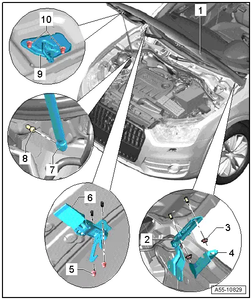
1 - Hood
- A second technician is needed to support and hold the hood during removal and installation.
- Removing:
- Unclip and remove the cover -4-.
- Engage the gas-filled strut on the hood. Refer to → Chapter "Gas-Filled Strut, Removing and Installing".
- Remove the nuts -3- from the upper hood hinge.
- Remove the hood.
- Install in reverse order of removal.
- Adjusting:
- Center the hood between the fenders.
- Adjust the height of the hood over the lower part of the lid lock.
- Adjust the gap between the hood and the fenders using the stop buffers.
2 - Lid Hinge
- Removing and installing. Refer to → Chapter "Hinges, Removing and Installing".
3 - Nut
- 25 Nm
4 - Cover
5 - Nut
- 8 Nm
6 - Hook
- Removing and installing. Refer to → Chapter "Center Catch, Removing and Installing".
7 - Gas-Filled Strut
- Removing and installing. Refer to → Chapter "Gas-Filled Strut, Removing and Installing".
- Install with tube end of strut at body.
8 - Ball Pin
- 21 Nm
9 - Catch
- Removing and installing. Refer to → Chapter "Catch, Removing and Installing".
10 - Nut
- 8 Nm
Overview - Gas-Filled Strut
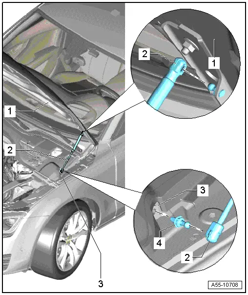
1 - Hood
2 - Gas-Filled Strut
- Removing and installing. Refer to → Chapter "Gas-Filled Strut, Removing and Installing".
3 - Ball Pin
- 21 Nm
4 - Ball Pin
- 21 Nm
Overview - Rear Lid Latch
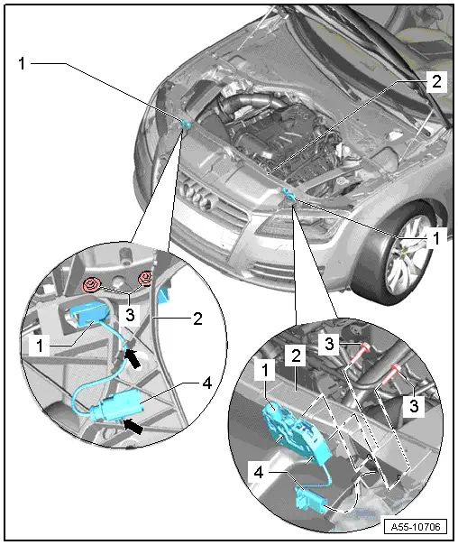
1 - Hood Latch
- Removing and installing. Refer to → Chapter "Hood Latch, Removing and Installing".
2 - Lock Carrier
3 - Bolt
- 11 Nm
4 - Hood Latch Electric Wire
READ NEXT:
 Overview - Release Cable
Overview - Latch Release Cable
1 - Right Hood Latch
Removing and installing. Refer to
→ Chapter "Hood Latch, Removing and Installing".
2 - Hood Latch Cable
R
Hood, Adjusting
Special tools and workshop equipment
required
Gauge - Gap Adjustment -3371-
Gap Dimensions for Hood
Note
All dimensions are in mm with a +- 0.5 mm tolerance.
Dimension -A- =
Release Cable, Removing and Installing
Release Cable Coupling
- Remove clips -1- and lift the release
cables -8- and -9-
on both sides toward the hood latches.
- To remove the coupling -2-, release the
retainers -arrows
SEE MORE:
Left Temperature Door Motor -V158-, Removing and Installing
Note
Only on vehicles with an automatic climate control system
For vehicles with a manual climate control system (or heater
without Air Conditioning (A/C) system), the temperature doors
are actuated by the Temperature Regulator Door Motor -V68-. The
right and left temperature do
Connector Assignments, Cell Phone Preparation Concert MOST, 9ZF
Information Electronics Control Module 1 -J794-
1 - Connector AM/FM1 from the Antenna Amplifier -R24- (Radio
Antenna 2 -R93-)
2 - DAB connection from Antenna Amplifier 4 -R113-, Digital
Radio Antenna -R183-
3 - Not installed
4 - Black connection block
© 2019-2026 Copyright www.auq3.net
