Audi Q3: Door, Adjusting
Special tools and workshop equipment required
- Gauge - Gap Adjustment -3371-
- Door Adjustment Template -T40038 /16-
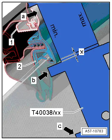
Check the Height Adjustment using the Door Adjustment Template -T40038 /16-.
- The template must lay on the top of the trim strip -1- as shown.
- The height is adjusted correctly when the bottom of the window guide -2- is inside the cut-out; x = 2.5 mm-arrow-.

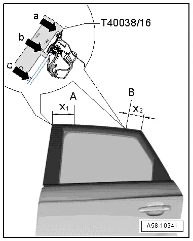
Check the Lateral Adjustment using the Door Adjustment Template -T40038 /16-.
- Place the template on check point -A- at -x1- = 150 mm or on check point -B- with a distance -x2- = 50 mm.
- For the "min" adjustment the template must be positioned on the upper edge of the upper roof trim molding -1-.
- The template must be touching points -b- and -c- when the adjustment is correct.
- At the point -a- there can be no gaps (to 0.8 mm).
- For the "max" adjustment the template must be positioned on the upper edge of the window guide-2-.
- The template must be touching points -a- and -c- when the adjustment is correct.
- The point -b- can have a gap (to 1.5 mm).
Rear Door Gap Dimension
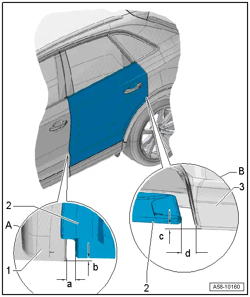
A - Rear Door to Front Door
- Gap dimension -a- = 4.4 +- 0.5 mm.
- Flush dimension -b- = 0 +- 1.0 mm
- Parallel alignment = 0.5 mm.
-1- Front door
-2- Rear door
- Adjusting. Refer to → Chapter "Door, Adjusting".
B - Rear Door to Rear Side Panel
- Gap dimension -d- = 3.4 +- 0.5 mm
- Flush -c- = 0 +- 1.0 mm
- Parallel alignment = 0.5 mm.
-2- Rear door
-3- Rear side panel
- Adjusting. Refer to → Chapter "Door, Adjusting".
Preliminary Work for Adjusting Lengthwise and Toward the Vehicle Center
- Remove the upper and lower B-pillar trim. Refer to → Body Interior; Rep. Gr.70; Passenger Compartment Trim; B-Pillar Trim, Removing and Installing.
- Remove the front three-point seat belt. Refer to → Body Interior; Rep. Gr.69; Seat Belts; Front Three-Point Seat Belt, Removing and Installing.
 WARNING
Follow all Safety Precautions when working with pyrotechnic components. Refer to → Body Interior; Rep. Gr.00; Safety Precautions; when working with Pyrotechnic Components.
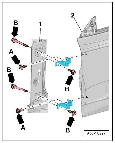
Adjustment in Longitudinal Direction
- Remove the upper and lower bolts -arrows B- from the hinge and B-pillar -1-.
- Adjust the door -2- lengthwise.
- Tighten the bolts -B arrows-.
Adjustment to Center of Vehicle
 Note
Note
- The bolt -A- is a fitting bolt so it is generally not necessary to adjust the door using it.
- If it is necessary to make an adjustment using these bolts, the bolt can be replaced with one of the same length and strength category.
- Loosen the bolts -A arrows- on the top and bottom of the hinge.
- Adjust the door -2- lengthwise.
- Tighten the bolts -A arrows-.
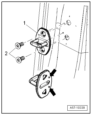
Catch, Adjusting
 Note
Note
- The striker pin backing must be position with the pins -arrows- exactly in the hole.
- The striker pins must be sheared off cleanly after sliding the striker pin.
- Loosen the bolts -2-.
- Slide the catch -1- until the door is flush with the body contours.
 Note
Note
- When adjusting the catch, move it only toward the center of the vehicle.
- Do not adjust the door height using the catch because the door lock will be damaged.
- The catch must align in door lock center for correct adjustment.
- Tighten the bolts -2-.
READ NEXT:
 Inner Door Seal, Removing and Installing
Removing
- Remove the rear sill panel strip. Refer to
→ Body Interior; Rep. Gr.70; Passenger Compartment Trim; Sill
Panel Strip, Removing and Installing.
- Remove the u
Overview - Window Regulator
1 - Door
2 - Window Regulator
Removing and installing. Refer to
→ Chapter "Window Regulator, Removing and Installing".
3 - Nut
6 Nm
4 -&nbs
Overview - Door Handle and Door Lock
Overview - Exterior Door Handle, Bracket
1 - Exterior Door Handle Trim
Removing and installing. Refer to
→ Chapter "Door Handle Trim, Removing and Installing".
2 -&nb
SEE MORE:
Driver Side Airbag
Overview - Driver Side Airbag
1 - Locking Bracket
Use a T25 TORX screwdriver, approximately 100 mm long
2 - Steering Column Electronics Control Module -J527-
With Airbag Spiral Spring/Return Spring with Slip Ring -F138- and
Steering Angle Sensor -G85-
Removing a
Speaker Ambient Lighting Bulb 1 and 2 -L211-/-L212-, Removing and Installing
Speaker Ambient Lighting Bulb 1 -L211-, Removing and Installing, Front
Door
Removing
- Remove the front door trim panel. Refer to
→ Body Interior; Rep. Gr.70; Front Door Trim Panels; Front Door
Trim Panel, Removing and Installing.
- Disconnect the connector -4-.
-
