Audi Q3: Component Location Overview - Storage Compartment/Covers
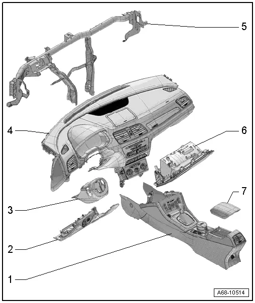
1 - Center Console
- Overview. Refer to → Chapter "Overview - Center Console".
2 - Driver Side Instrument Panel Cover
- Overview. Refer to → Chapter "Overview - Driver Side Instrument Panel Cover".
3 - Trim Panel
- For the steering column switch module
- Overview. Refer to → Chapter "Overview - Steering Column Trim Panel".
4 - Instrument Panel
 WARNING
Follow all safety precautions when working with pyrotechnic components. Refer to → Chapter "Pyrotechnic Components Safety Precautions".
- Overview. Refer to → Chapter "Overview - Instrument Panel".
5 - Central Tube
- For the instrument panel
- Overview. Refer to → Chapter "Overview - Instrument Panel Central Tube".
6 - Glove Compartment
- Overview. Refer to → Chapter "Overview - Glove Compartment".
7 - Front Center Armrest
- Overview. Refer to → Chapter "Overview - Front Center Armrest".
Overview - Driver Side Instrument Panel Cover
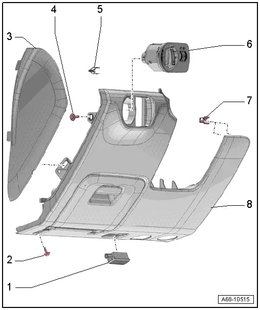
1 - Left Footwell Lamp -W9-
- Equipment levels
- Removing and installing. Refer to → Electrical Equipment; Rep. Gr.96; Lamps; Left Footwell LampW9/Right Footwell Lamp W10, Removing and Installing.
2 - Bolt
- 3 Nm
- Quantity 1 or 2 depending on the version
3 - Side Cover
- For the instrument panel
- Removing and installing. Refer to → Chapter "Instrument Panel Side Cover, Removing and Installing".
4 - Bolt
- 3 Nm
5 - Spring Clip
- For the driver side instrument panel cover
- Replace damaged or deformed spring clip
- Place in the instrument panel cover
6 - Light Switch -E1-
- Removing and Installing. Refer to → Electrical Equipment; Rep. Gr.96; Controls; Component Location Overview - Controls in the Instrument Panel.
7 - Spring Clamp
- For the driver side instrument panel cover
- Quantity: 5
- Replace damaged or deformed spring clips
- Press into the instrument panel
8 - Driver Side Instrument Panel Cover
- Removing and installing. Refer to → Chapter "Driver Side Instrument Panel Cover, Removing and Installing".
Overview - Steering Column Trim Panel
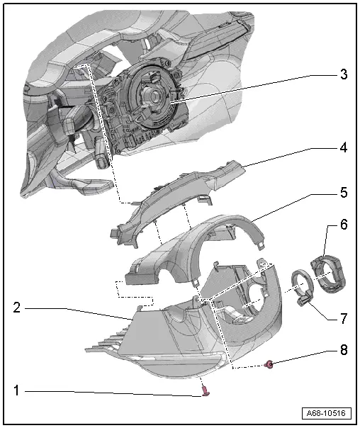
1 - Bolt
- 2.5 Nm
2 - Lower Trim Panel
- For the steering column switch module
- Removing and installing. Refer to → Chapter "Lower Steering Column Trim Panel, Removing and Installing".
3 - Steering Column Switch Module
- Removing and installing. Refer to → Electrical Equipment; Rep. Gr.94; Steering Column Switch Module; Steering Column Switch Module, Removing and Installing.
4 - Gap Cover
- For instrument cluster
- Removing and installing. Refer to → Chapter "Instrument Cluster Gap Cover, Removing and Installing".
- Press on until it engages audibly.
5 - Upper Trim Panel
- For the steering column switch module
- Removing and installing. Refer to → Chapter "Upper Steering Column Trim Panel, Removing and Installing".
6 - Mount
- For the reading coil
- Removing and installing. Refer to → Electrical Equipment; Rep. Gr.96; Immobilizer; Anti-Theft Immobilizer Reader Coil, Removing and Installing.
7 - Anti-Theft Immobilizer Reader Coil -D2-
- Equipment levels
- Removing and installing. Refer to → Electrical Equipment; Rep. Gr.96; Immobilizer; Anti-Theft Immobilizer Reader Coil, Removing and Installing.
8 - Bolt
- 2.5 Nm
- Quantity: 2
Overview - Glove Compartment
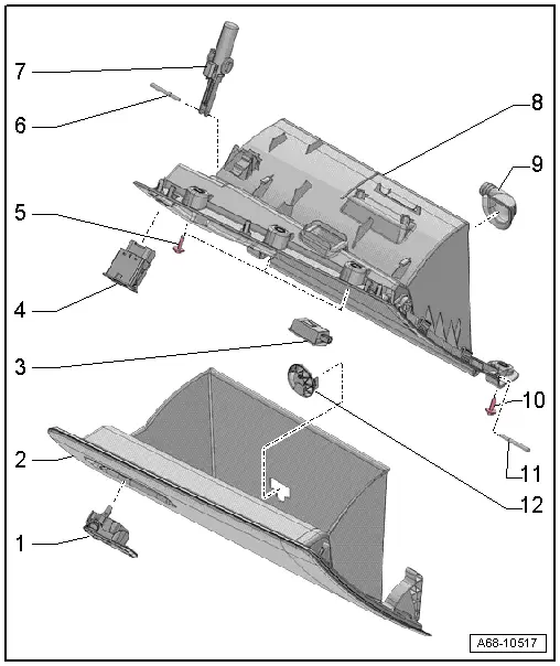
1 - Glove Compartment Opener
- Removing and installing. Refer to → Chapter "Glove Compartment Handle, Removing and Installing".
- Press into the glove compartment cover until it engages audibly
2 - Glove Compartment Lid with Storage Compartment
- Activate the glove compartment cover emergency release. Refer to → Chapter "Glove Compartment Lid Emergency Release, Operating".
- Removing and installing. Refer to → Chapter "Glove Compartment Lid, Removing and Installing".
3 - Glove Compartment Lamp -W6-
- Removing and Installing. Refer to → Electrical Equipment; Rep. Gr.96; Lamps; Glove Compartment LampW6 Removing and Installing.
4 - Front Passenger Airbag Deactivation Key Switch -E224-
NOT FOR NORTH AMERICAN MARKET
5 - Bolt
- 3 Nm
- Quantity: 3
6 - Hinge Pin
- For the brake component
7 - Lid Dampening Mechanism
- For the glove compartment lid
- With Glove Compartment Lamp Switch -E26-
- Removing and installing. Refer to → Chapter "Glove Compartment Lid Dampening Mechanism, Removing and Installing".
8 - Glove Compartment
- Removing and installing. Refer to → Chapter "Glove Compartment, Removing and Installing".
9 - Connection for Glove Compartment Cooling
- Equipment levels
10 - Bolt
- 3 Nm
- Quantity: 3
11 - Hinge Pin
- Quantity: 2
- For the glove compartment lid
12 - Vent for Glove Compartment Cooling
- Equipment levels
- Blind cover for vehicles without glove compartment cooling
READ NEXT:
 Driver Side Instrument Panel Cover, Removing and Installing
Note
As a replacement part, the new cover is delivered with an
additional attaching point.
Special tools and workshop equipment
required
Wedge Set -T10383-
Removing
- Remov
Glove Compartment Handle, Removing and Installing
Special tools and workshop equipment
required
Locking Pin (3 pc.) -T40011-
Removing
Note
If glove compartment cover does not open, it can be opened
via the emergency release. Ref
Equipment
Overview - Sun Visors
1 - Sun Visor
Allocation. Refer to the Parts Catalog.
Removing and installing. Refer to
→ Chapter "Sun Visor, Removing and Installing".
Insert visorSEE MORE:
Settings
Telephone settings
Applies to: vehicles with telephone
Applies to: MMI: Select on the home screen:
PHONE > .
The following options may be possible, depending
on your mobile device:
Decline with text message
Edit voicemail number
Switching between two mobile devices
Requirement: phone 1 an
Settings
Wi-Fi
Applies to: vehicles with Wi-Fi hotspot
Depending on the country and the vehicle equipment,
the following functions may be available:
Wi-Fi
When the function is switched on, the MMI's Wi-Fi hotspot is active and Wi-Fi
devices can be connected
to the hotspot.
Wi-Fi hotspot settings
The Wi-Fi c