Audi Q3: Ball Joint, Removing and Installing
Special tools and workshop equipment required
- Puller - Ball Joint -3287A-
- Digital Torque Wrench -VAG1756A-
- Torque Wrench 1332 Insert - Ring Wrench - 18mm -VAG1332/10-
Removing
- Loosen drive axle bolt on the wheel hub. Refer to → Chapter "Drive Axle Threaded Connection, Loosening and Tightening".
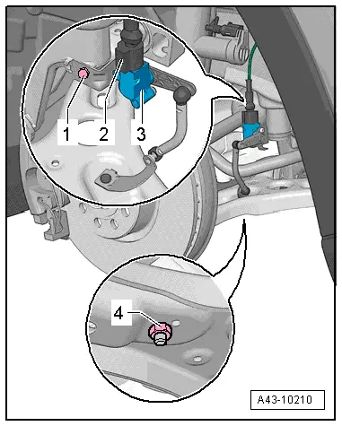
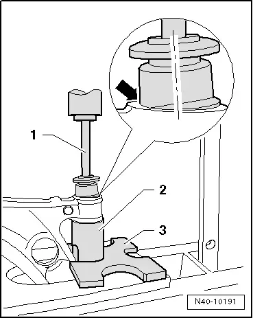
- Remove the nut -4- and free up the coupling rod from the Left Front Level Control System Sensor -G78- or Right Front Level Control Sensor -G289--3-.
- Remove the front wheel. Refer to → Chapter "Wheels and Tires".
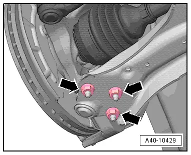
- Remove the nuts -arrows- from the ball joint.
- Remove the control arm from the ball joint.
 Note
Note
Pay attention during the assembly work that the ball joint rubber boot is not damaged. If necessary protect the ball joint rubber boot against damage.
- Pivot the suspension strut outward, while doing so guide the drive axle out of the wheel hub.
 Note
Note
Do not let the drive axle hang down. The inner joint could be damaged if it is bent too far.
- Secure the drive axle to the body with wire.
- Loosen the nuts on the ball joint, but do not remove.
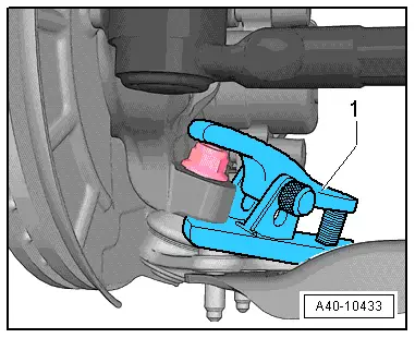
- Attach the Puller - Ball Joint -3287A--1- as shown and press out the ball joint.
 Note
Note
Place the Engine and Gearbox Jack -VAS6931- or something similar underneath (danger of accident if parts fall off when ejecting ball joint).
 WARNING
When pressing off, the ball joint loosens itself from the wheel bearing housing abruptly - risk of accident!
- Remove the nut from the ball joint and remove the ball joint.
Installing
Installation is reverse of removal, noting the following:
- Guide the drive axle into the wheel hub splines.
- Tighten the drive axle: For the procedure for tightening the twelve-point bolt. Refer to → Chapter "Drive Axle Threaded Connection, Loosening and Tightening".
- Install the front wheel. Refer to → Chapter "Wheels and Tires".
- An axle alignment may be required. Refer to → Chapter "Evaluating Need for Axle Alignment".
- On vehicles with electronically controlled damping, perform the function "Adapt the control position" with the Vehicle Diagnosis Tester.
- If the control position was reprogrammed and if the vehicle has lane assist, then it will then be necessary to calibrate the driver assistance systems front camera. Refer to → Chapter "Driver Assistance Systems Front Camera, Calibrating".
- On vehicles with level control system sensor, perform headlamp basic setting. Refer to → Electrical Equipment; Rep. Gr.94; Headlamp, Adjusting.
Lower Control Arm Bonded Rubber Bushing, Replacing
Special tools and workshop equipment required
- Wishbone Rubber Mount Assembly Tool -T10219-
- Press Plate -VW402-
- Press Piece - Rod -VW411-
- Installation Lubricant -G 294 421 A1-. Refer to the Parts Catalog.
Pressing out the bonded rubber bushing
- Control arm removed. Refer to → Chapter "Lower Control Arm, Removing and Installing".
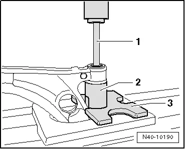
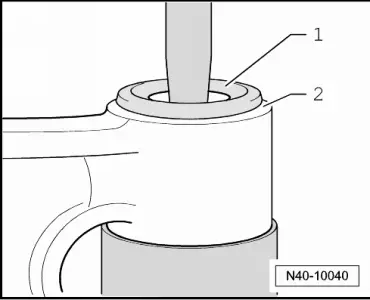
- Press out bonded rubber bushings as depicted in the illustration.
1 - Press Piece - Rod -VW411-
2 - Wishbone Rubber Mount Assembly Tool - Tube -T10219/1-
3 - Press Plate -VW402-
Installing the bonded rubber bushing
- Bonded rubber bushing must be installed at an angle to prevent damaging it when pressing in. Bonded rubber bushing sets straight while pressing in.
- Apply Installation Lubricant -G 294 421 A1- onto the outside of the bonded rubber bushing.
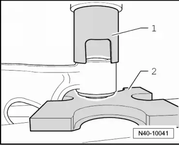
- Place bonded rubber bushing on at an angle (in direction of control arm),when doing this the lip must slip into hole.
1 - Wishbone Rubber Mount Assembly Tool - Drift -T10219/2-
2 - Wishbone Rubber Mount Assembly Tool - Tube -T10219/1-
3 - Press Plate -VW402-
- Install the bonded rubber bushings until the core -1- and the mounting bracket opening -2- are at the same height.
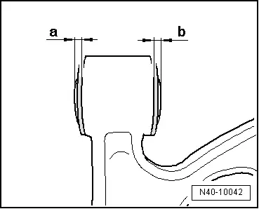
- Press back bearing slightly in control arm.
1 - Wishbone Rubber Mount Assembly Tool - Tube -T10219/1-
2 - Press Plate -VW402-
Dimensions -a- and -b- must be identical.
READ NEXT:
 Overview - Wheel Bearing
1 - Suspension Strut
2 - Bolt
70 Nm + 90º
Always replace if removed
Bolt point must face in direction of travel.
3 - Front Speed Sensor
Removing and in
Wheel Bearing Housing, Removing and Installing
Special tools and workshop equipment
required
Puller - Ball Joint -3287A-
Torque Wrench 1332 40-200Nm -VAG1332-
Engine and Gearbox Jack -VAS6931-
Digital Torque Wrench -VAG1756A-
Spreade
Wheel Bearing Unit, Removing and Installing
Special tools and workshop equipment
required
Torque Wrench 1332 40-200Nm -VAG1332-
Removing
- Loosen the drive axle threaded connection on the wheel side.
Refer to
→ ChapterSEE MORE:
Correct safety belt positioning
Fig. 58 Lap/shoulder belt positioning
Fig. 59 Safety belt positioning for pregnant women
Fastened safety belts only offer optimal protection
during an accident and reduce the risk of serious
injury or death when they are positioned
correctly. Furthermore, the correct safety belt
position holds the
Bluetooth audio player
Applies to: vehicles with Bluetooth audio player
With the Bluetooth audio player, you can play
music wirelessly through the MMI from your
Bluetooth-capable mobile device (such as a cell
phone).
Requirement: the vehicle must be stationary and
the ignition must be switched on. The Bluetooth
settings 