
Audi Q3: Start/Stop System
Component Location Overview - Start/Stop System
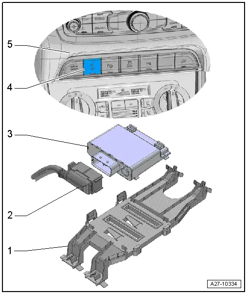
1 - Bracket
- For the Voltage Stabilizer -J532-
2 - Connector
3 - Voltage Stabilizer -J532-
- Removing and installing. Refer to → Chapter "Voltage Stabilizer, Removing and Installing".
4 - Start/Stop Mode Button -E693-
- Removing and installing. Refer to → Chapter "Lower Left Instrument Panel Button Unit, Removing and Installing".
5 - Instrument Panel
Voltage Stabilizer, Removing and Installing
Removing
- Turn off the ignition.
- Vehicles with ignition lock: Remove the key.
- Remove the left front seat. Refer to → Body Interior; Rep. Gr.72; Front Seats; Front Seat, Removing and Installing.
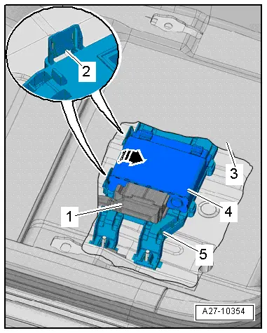
- Cut the carpet -3- in the area of the cover with scissors along the perforation and fold to the side.
- Release the tabs -2- and pivot the Voltage Stabilizer -J532--4- from the bracket -5- in direction of -arrow-.
- Disconnect the connector -1-.
Installing
Install in reverse order of removal. Note the following:
- Install the front seat. Refer to → Body Interior; Rep. Gr.72; Front Seats; Front Seat, Removing and Installing.
Special Tools
Special tools and workshop equipment required
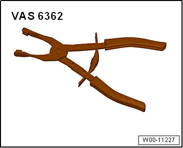
- Hose Clip Pliers -VAS6362-
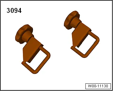
- Hose Clamps - Up To 25mm -3094-
READ NEXT:
 Instrument Cluster
Overview - Instrument Cluster
1 - Outside Air Temperature Sensor -G17-
Removing and installing. Refer to
→ Chapter "Outside Air Temperature Sensor, Removing and Installing".
Fuel Level Sensor Connector Assignment
Fuel Level Sensor -G- Connector Assignment
Disconnect the connector on the fuel tank locking flange.
For the procedure. Refer to
→ Rep. Gr.20; Fuel Delivery Unit/Fuel Level Sensor; FuSEE MORE:
Glass Panel, Removing and Installing
Panel 1 for the Panorama Roof, Removing
Caution
Do not move or operate the already removed panel
otherwise it may become damaged.
Note
If the screws for the panel mounting were completely
removed, then they must be replaced.
1 - Bolt
7 Nm
Front and rear,
Lower Rear Lid Trim Panel, Removing and Installing
Lower Rear Lid Trim Panel, Removing and Installing
Special tools and workshop equipment
required
Pry Lever -80-200-
Omega Clip Tool -T40280-
Removing
- If installed, remove the rear shelf. Refer to
→ Chapter "Rear Shelf Rear Section, Removing and Installing".
- Remove