Audi Q3: Fuel Level Sensor Connector Assignment
Fuel Level Sensor -G- Connector Assignment
Disconnect the connector on the fuel tank locking flange. For the procedure. Refer to → Rep. Gr.20; Fuel Delivery Unit/Fuel Level Sensor; Fuel Delivery Unit/Fuel Level Sensor Assembly Overview.
 Note
Note
Check the exact assignment in the current wiring diagram. Refer to → Wiring diagrams, Troubleshooting & Component locations.
Fuel Level Sensor 2 -G169- Connector Assignment
Disconnect the connector on the fuel tank locking flange. For the procedure. Refer to → Rep. Gr.20; Fuel Delivery Unit/Fuel Level Sensor; Fuel Level Sensor 2G169, Checking.
 Note
Note
Check the exact assignment in the current wiring diagram. Refer to → Wiring diagrams, Troubleshooting & Component locations.
Engine Coolant Temperature Sensor Connector Assignment
Engine Coolant Temperature Sensor -G62- Connector Assignment
Disconnect the connector on the Engine Coolant Temperature Sensor -G62-. Procedure. Refer to → Rep. Gr.19; Coolant Pump/Coolant Regulation.
 Note
Note
Check the exact assignment in the current wiring diagram. Refer to → Wiring diagrams, Troubleshooting & Component locations.
Engine Coolant Temperature Sensor on Radiator Outlet -G83- Connector Assignment - TDI-Engines
Disconnect the connector on the Engine Coolant Temperature Sensor On Radiator Outlet -G83-. For the procedure. Refer to → Rep. Gr.19; Coolant Pump/Thermostat - the sensor is not removed.
 Note
Note
Check the exact assignment in the current wiring diagram. Refer to → Wiring diagrams, Troubleshooting & Component locations.
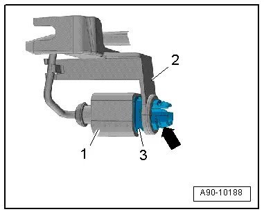
Outside Air Temperature Sensor, Removing and Installing
Removing
- Reach through the opening on the radiator grille and carefully push the retaining tabs together -arrow-, while doing so remove the Outside Air Temperature Sensor -G17--3- from the bracket -2-.
- Disconnect the connector -1-.
Installing
Install in reverse order of removal.
Clock
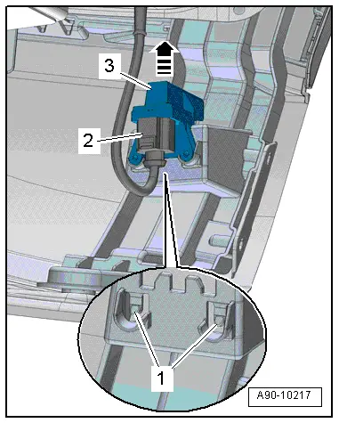
Radio Frequency Controlled Clock Receiver, Removing and Installing
Removing
- Disconnect the connector -2- on the Radio Frequency Controlled Clock Receiver -J489-.
- Carefully push the retaining clips -1- rearward and at the same time remove the Radio Frequency Controlled Clock Receiver -J489--3- upward from the mount in direction of -arrow-.
Installing
Install in reverse order of removal. Note the following:
- Push the Radio Frequency Controlled Clock Receiver -J489- until it audibly locks in the mount.
READ NEXT:
 Horn
Horn
Overview - Horn
1 - Nut
9 Nm
2 - Nut
9 Nm
3 - Low Tone Horn -H7-
Removing and installing. Refer to
→ Chapter "High Tone Horn -H2-/Low Tone H
Windshield Wiper System
Overview - Windshield Wiper System
Overview - Windshield Wiper System
1 - Bolt
Tightening sequence. Refer to → Fig. " Windshield Wiper
Motor -V- - Tightening Specification SEE MORE:
Front Brake Caliper, Replacing
Brake Caliper, Replacing,1LJ, 1 ZD Brakes
Note
In the following description the brake caliper is removed
and replaced. The brake hose is removed.
Special tools and workshop equipment
required
Torque Wrench 1331 5-50Nm -VAG1331-
Brake Pedal Actuator -VAG1869/2-.
Container -1-
Steering Column
Overview - Steering Column
Note
Always replace corroded bolts/nuts.
1 - Instrument Panel Central Tube
2 - Shear Bolt
Tighten the shear bolt until head shears off.
3 - Steering Column
Removing and installing. Refer to
→ Chapter "Steerin