Audi Q3: Overview - Door
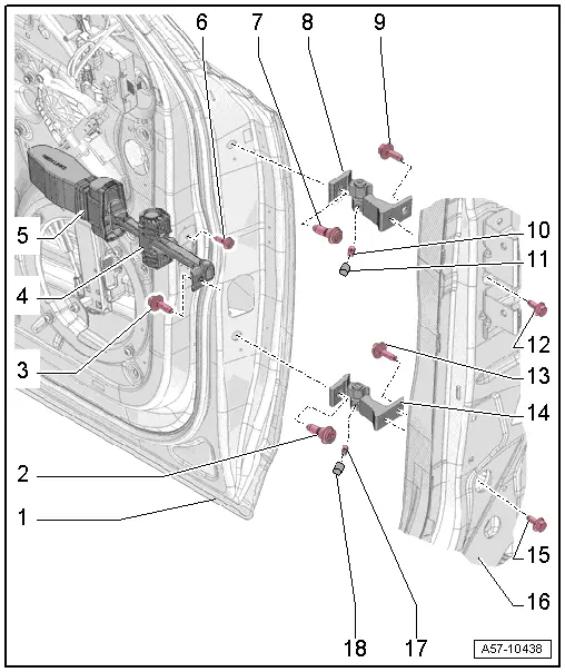
1 - Door
- Removing and installing. Refer to → Chapter "Door, Removing and Installing".
2 - Bolt
- 45 Nm
 Note
Note
- The bolt is a fitting bolt so it is generally not necessary to adjust the door using it.
- If it is necessary to make an adjustment using these bolts, the bolt can be replaced with one of the same length and strength category.
3 - Bolt
- 33 Nm
4 - Door Arrester
- Removing and installing. Refer to → Chapter "Door Arrester, Removing and Installing".
5 - Cap
- For the door arrester
- Observe installation direction
6 - Bolt
- 8 Nm
- Quantity: 2
7 - Bolt
- 45 Nm
 Note
Note
- The bolt is a fitting bolt so it is generally not necessary to adjust the door using it.
- If it is necessary to make an adjustment using these bolts, the bolt can be replaced with one of the same length and strength category.
8 - Upper Door Hinge
9 - Bolt
- 32 Nm
10 - Stud Bolt
- 23 Nm
11 - Cap
- Place on the stud bolt
12 - Bolt
- 32 Nm
13 - Bolt
- 32 Nm
14 - Lower Door Hinge
15 - Bolt
- 32 Nm
16 - A-Pillar
17 - Stud Bolt
- 23 Nm
18 - Cap
- Place on the stud bolt
Overview - Door Seals
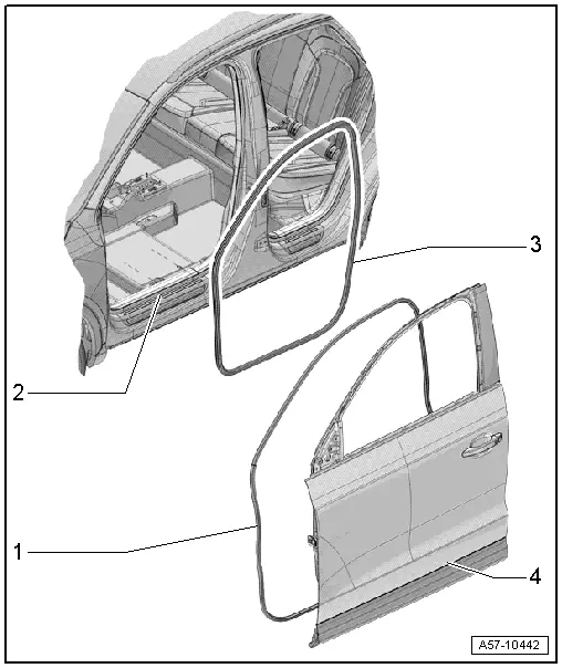
1 - Outer Door Seal
- Removing and installing. Refer to → Chapter "Outer Door Seal, Removing and Installing".
2 - Body
3 - Inner Door Seal
- Removing and installing. Refer to → Chapter "Inner Door Seal, Removing and Installing".
4 - Door
READ NEXT:
 Door, Removing and Installing
Removing
- Disconnect the door connector on the A-pillar. Refer to
→ Electrical Equipment; Rep. Gr.97; Connectors.
Note
Secure the A-pillar in the area of the door a
Door, Adjusting
Special tools and workshop equipment
required
Gauge - Gap Adjustment -3371-
Door Adjustment Template -T40038 /16-
Check the height adjustment using the Door Adjustment
Template -T40038 /1
Inner Door Seal, Removing and Installing
Removing
- Remove the upper A-pillar trim. Refer to
→ Body Interior; Rep. Gr.70; Passenger Compartment Trim;
A-Pillar Trim, Removing and Installing.
- Remove the front SEE MORE:
Lane Change Assistance
Overview - Lane Change Assistance
1 - Lane Change Assistance Button -E530-
Removing and installing. Refer to
→ Chapter "Lane Change Assistance Button -E530-, Removing and
Installing".
2 - Lane Change Assistance Warning Lamp In Driver Exterior Rearview
Mirro
Component Location Overview - Components Inside Front Passenger
Compartment
Component Location Overview - Components Inside Front Passenger
Compartment, Left Side of Passenger Compartment
1 - Left Footwell Vent
Overview. Refer to
→ Chapter "Overview - Air Routing and Air Distribution in Passenger
Compartment, Front Air Guides".
2 -
© 2019-2026 Copyright www.auq3.net | 0.01
