Audi Q3: Overview - Antenna Systems
Communication / Electrical System / Audi Q3 (8U) 2011-2018 Service Manual / Overview - Antenna Systems
The antenna system consists of the Roof Antenna -R216- and the window antenna.
Roof Antenna -R216-
- GPS Antenna -R50-, only on 7T2, 7T6 and 7Q4
- Telephone Antenna -R65-, only on 9ZF and 9ZW
- Satellite Antenna -R170-, only North America and QV8
- Auxiliary Heater Antenna -R182-, only Europe and 9M9
Rear Window Antennas
- Digital Radio Antenna -R183- (DAB) to the Antenna Amplifier 4 -R113- on the right top of the rear lid near the Radio MOST
- Antenna -R11- (FM2) Antenna Amplifier 3 -R112- on the bottom left of the rear lid.
- Radio Antenna 2 -R93- (AM/FM1)/TV Antenna 1 -R55- (TV1) Antenna Amplifier -R24- on upper left of rear lid.
- TV Antenna 2 -R56- (TV2)/TV Antenna 3 -R57- (TV3) Antenna Amplifier 2 -R111- at the bottom of the right of the rear lid.
The Antenna Amplifier 4 -R113- with the DAB connection is only applicable to Europe and QV3.
Windshield Antenna
- Traffic Data Antenna -R173- ETC/VICS only Japan, 7T6
In the Instrument Panel
- Internet Antenna -R266-, W-LAN, UE2
Repairing the antenna wires. Refer to → Electrical Equipment General Information; Rep. Gr.97; Antenna Wires, Repairing.
Component Location Overview - Antenna Systems
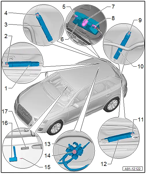
1 - Antenna Amplifier 4 -R113-
- Connector assignment.
- Removing and installing. Refer to → Chapter "Antenna Amplifier 4 -R113-, Removing and Installing".
2 - Bolt
- 2 Nm
3 - Antenna Amplifier 2 -R111-
- Connector assignment.
- Removing and installing. Refer to → Chapter "Antenna Amplifier 2 -R111-, Removing and Installing".
4 - Bolt
- 2 Nm
5 - Nut
- 9 Nm
6 - Windshield Antenna Suppression Filter -C18-
- Removing and installing. Refer to → Chapter "Windshield Antenna Suppression Filter -C18-, Removing and Installing".
7 - Nut
- 9 Nm
8 - Nut
- 9 Nm
9 - Bolt
- 2 Nm
10 - Antenna Amplifier 3 -R112-
- Connector assignment.
- Removing and installing. Refer to → Chapter "Antenna Amplifier 3 -R112-, Removing and Installing".
11 - Bolt
- 2 Nm
12 - Antenna Amplifier -R24-
- Connector assignment.
- Removing and installing. Refer to → Chapter "Antenna Amplifier -R24-, Removing and Installing".
13 - Roof Antenna -R216-
- Removing and installing. Refer to → Chapter "Roof Antenna, Removing and Installing".
14 - Nut
- 6 Nm
15 - Safety piece
16 - Traffic Data Antenna -R173-
- Removing and installing. Refer to → Chapter "Windshield Antenna Suppression Filter -C18-, Removing and Installing".
17 - Bracket
- Glued to the windshield
READ NEXT:
 Antenna Amplifier, Removing and Installing
Antenna Amplifier -R24-, Removing and Installing
The Antenna Amplifier -R24- is located on the upper left of
the rear lid.
Removing
- Turn off the ignition and all electrical equipment and
Roof Antenna, Removing and Installing
The Roof Antenna -R216- has up to three connectors.
The antenna wires are connected directly to the base of the
Roof Antenna -R216-.
The headliner must be lowered in order to remove the Roof
Ant
Antenna Amplifier Connector Assignments
Antenna Amplifier 4 -R113-
1 - Window antenna connection, Digital Radio Antenna -R183-
2 - DAB connection to the Radio -R-
3 - Not Assigned
Window Antenna ConnectorSEE MORE:
General information
Selecting the radio
Fig. 136 Center display: FM station list
Fig. 137 Center display: SiriusXM station list
Depending on the vehicle equipment, the radio
may support the FM, AM, and SiriusXM (satellite
radio) frequency bands. Using the HD Radio receiver
also allows you to receive radio stations
on
Overview - Rear Outer Three-Point Seat Belt
1 - Belt Guide
Caution
Do not rotate bolts under any circumstances when removing
and installing belt guide. They are set by the manufacturer.
Replace the entire belt guide if damaged.
Removing and installing. Refer to
→ Chapter "Rear Seat Belt Guide, Rem
© 2019-2026 Copyright www.auq3.net | 0.0095
