Audi Q3: Antenna Amplifier Connector Assignments
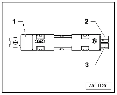
Antenna Amplifier 4 -R113-
1 - Window antenna connection, Digital Radio Antenna -R183-
2 - DAB connection to the Radio -R-
3 - Not Assigned

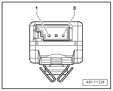
Window Antenna Connector
1 - L-Band
2 - Band III
3 - Diag.

Antenna Amplifier -R24-
1 - Window antenna connection, Radio Antenna 2 -R93-/TV Antenna 1 -R55-
2 - AM/FM1 connection to the Radio -R-
3 - TV1 connection to the TV Tuner -R78-

Window Antenna Connector
1 - Radio Antenna 2 -R93-, AM
2 - Radio Antenna 2 -R93-/TV Antenna 1 -R55-, FM1/TV1/Diag.
3 - Diag.
Antenna Amplifier 3 -R112-
1 - Window antenna connection, Antenna -R11-
2 - Connection FM2, to the Radio -R-
3 - Not Assigned

Window Antenna Connector
1 - Not Assigned
2 - Antenna -R11-, FM2/Diag.
3 - Not Assigned

Antenna Amplifier 2 -R111-
1 - Window antenna connection, TV Antenna 2 -R56-/TV Antenna 3 -R57-
2 - TV3 connection to the TV Tuner -R78-
3 - TV2 connection to the TV Tuner -R78-
Window Antenna Connector
1 - TV Antenna 3 -R57-, TV3
2 - TV Antenna 2 -R56-, TV2/Diag.
3 - Not Assigned

Roof Antenna -R216- Connector Assignments
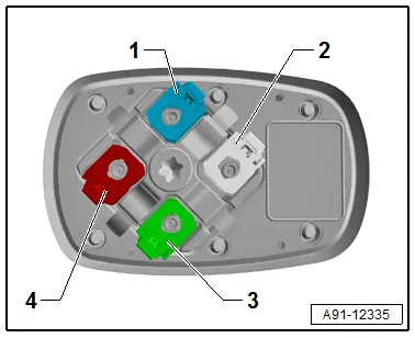
Roof Antenna -R216-
1 - GPS Antenna -R50-, blue
2 - Not assigned, white
3 - Auxiliary Heater Antenna -R182-, green
4 - Telephone Antenna -R65-, bordeaux
Only North America and QV8
1 - GPS Antenna -R50-, blue
2 - Not assigned, white
3 - Satellite Antenna -R170-, green
4 - Telephone Antenna -R65-, bordeaux
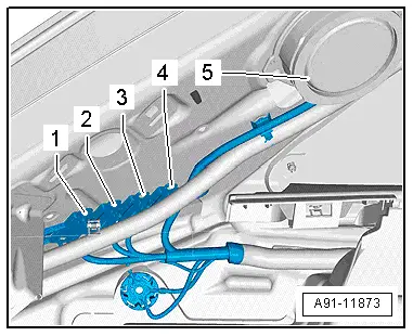
Antenna Wire Coupling Point
A coupling is installed on the lower left D-pillar underneath the Left Rear Speaker -R4- for the Antenna Amplifier -R24-, Antenna Amplifier 3 -R112- and Antenna Amplifier 4 -R113- antenna wire.
Coupling Point
1 - Not Assigned
2 - Antenna Amplifier -R24-
3 - Antenna Amplifier 3 -R112-
4 - Antenna Amplifier 4 -R113-
5 - Left Rear Speaker -R4-
READ NEXT:
 Overview - Radio Components
Overview - Radio, Radio Chorus, CAN, 8UA
Radio with integrated CD player
Sound system: basic, 8RE
Optional
Sound system: basic plus, 8RX
Cell Phone Preparation Preliminary Setup
The
Radio, Removing and Installing
Radio, Removing and Installing, Radio Chorus, 8UA
The Radio -R- is located in the instrument panel.
Note
If replacing the control module, select the "Replace control
module" function forSEE MORE:
Overview - Front Backrest
Overview - Front Backrest, Standard Seat/Sport Seat
1 - Seat Pan
2 - Bolt
33 Nm
Quantity: 2
Self-locking
Replace
Threaded holes for bolts must be cleaned, for example, with a thread
tap
3 - Backrest
Removing and installing. Refer to
→ C
Drive Axle, Removing and Installing, Drive Axle with Bolted CV Joint VL
107
Removing
- Loosen the drive axle threaded connection on the wheel side.
Refer to
→ Chapter "Drive Axle Threaded Connection, Loosening and
Tightening".
- Remove the front wheel. Refer to
→ Chapter "Wheels and Tires".
- Remove the noise insulation -1-.
Refer t