Audi Q3: Stabilizer Bar
Overview - Stabilizer Bar
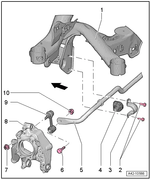
1 - Subframe
2 - Bolt
- 25 Nm + 45º
- Always replace if removed
- Install evenly
3 - Clamp
4 - Bearing
- Always replace the rubber mounts on both sides of vehicle
5 - Stabilizer Bar
- Removing and installing. Refer to → Chapter "Stabilizer Bar, Removing and Installing".
6 - Bolt
7 - Nut
- 40 Nm
- Counterhold at the inner multipoint fitting when tightening
8 - Wheel Bearing Housing
9 - Coupling Rod
10 - Nut
- 40 Nm
- Counterhold at the inner multipoint fitting of the bolt -item 6-, when tightening
- Tighten in the curb weight position. Refer to → Chapter "Wheel Bearing in Curb Weight, Lifting Vehicles with Coil Spring".
Stabilizer Bar, Removing and Installing
Special tools and workshop equipment required
- Torque Wrench 1331 5-50Nm -VAG1331-
Removing
- Remove the rear wheels. Refer to → Chapter "Wheels and Tires".
 Note
Note
The following work steps are described for the left side of the vehicle. These work steps also apply simultaneously for right side of vehicle.
- Remove the nut -1- and pull the coupling rod -2- out of the stabilizer bar.

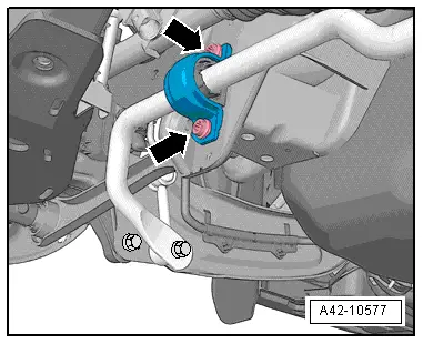
- Remove the bolts -arrows- for the stabilizer bar clamp.
- If the upper bolt for the stabilizer bar clamp cannot be removed due to the driveshaft, perform the following steps:

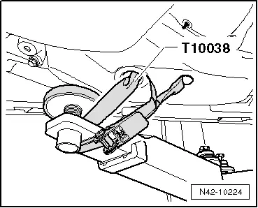
- Secure both sides of the vehicle on the hoist arms using Tensioning Straps -T10038-.
 WARNING
The vehicle could slide off the hoist if it is not secured.
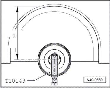
- Install Engine/Gearbox Jack Adapter - Wheel Hub Support -T10149- with wheel bolt on wheel hub.
- Lift the wheel hub using the Engine/Gearbox Jack Adapter - Wheel Hub Support -T10149- and Engine and Gearbox Jack -VAS6931- far enough until the bolts on the right stabilizer bar clamp are accessible.
- Remove the stabilizer bar.
Installing
Installation is reverse of removal, noting the following:
- Tighten the bolts -arrows- for stabilizer clamp uniformly.
- Counterhold at the inner multipoint fitting when tightening the coupling rod bolts.
- Mount the rear wheels. Refer to → Chapter "Wheels and Tires".
- An axle alignment may be required. Refer to → Chapter "Evaluating Need for Axle Alignment".
Coupling Rod, Removing and Installing
Special tools and workshop equipment required
- Torque Wrench 1331 5-50Nm -VAG1331-
Removing
- Remove the rear wheel. Refer to → Chapter "Wheels and Tires".
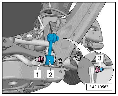
- Remove the nuts -1 and 3- and pull the coupling rod -2- out of the stabilizer bar and trailing arm.
Installing
Installation is reverse of removal, noting the following:
- Insert the coupling rod -2-, install the nuts -1 and 3- and tighten in curb weight position. Refer to → Chapter "Wheel Bearing in Curb Weight, Lifting Vehicles with Coil Spring".
- When tightening the nuts -1 and 3-, counterhold at the inner multipoint fitting of the bolts.
- Mount the rear wheel. Refer to → Chapter "Wheels and Tires".

READ NEXT:
 Overview - Transverse Link
1 - Stone Chip Protection
For allocation. Refer to the Parts Catalog.
2 - Lower Transverse Link
Removing and installing. Refer to
→ Chapter "Lower Transverse
Upper Transverse Link, Removing and Installing
Upper Transverse Link, Removing and Installing, FWD Vehicles
Special tools and workshop equipment
required
Torque Wrench 1332 40-200Nm -VAG1332-
Removing
- Measure dimension from cente
Lower Transverse Link, Removing and Installing
Lower Transverse Link, Removing and Installing, FWD Vehicles
Special tools and workshop equipment
required
Torque Wrench 1332 40-200Nm -VAG1332-
Removing
- Measure dimension from centeSEE MORE:
myAudi navigation
Applies to: vehicles with myAudi navigation
MMI navigation works seamlessly with the myAudi
app.
Your destinations (favorites, last destinations)
are synchronized through your myAudi account.
All important destinations can be displayed in
the vehicle and in the myAudi app.
To load destinations in
Inner Window Shaft Strip, Removing and Installing
Removing
- Remove the rear window frame trim panel. Refer to
→ Body Interior; Rep. Gr.70; Rear Door Trim Panels; Window Frame
Trim Panel, Removing and Installing.
- Remove the window shaft strip -1-
upward -arrows-.
Installing
Install in reverse order of removal