
Audi Q3: Overview - Wheel Bearing
Suspension, Wheels, Steering / Chassis / Audi Q3 (8U) 2011-2018 Service Manual / Overview - Wheel Bearing
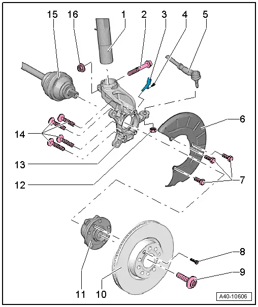
1 - Suspension Strut
2 - Bolt
- 70 Nm + 90º
- Always replace if removed
- Bolt point must face in direction of travel.
3 - Front Speed Sensor
- Removing and installing. Refer to → Brake System; Rep. Gr.45; Sensors; Front ABS Wheel Speed Sensor G45/G47, Removing and Installing.
4 - Bolt
- Tightening specification. Refer to → Brake System; Rep. Gr.45; Sensors; Overview - Front Axle Speed Sensor.
5 - Tie Rod End
6 - Brake Shield
7 - Bolt
- For the tightening specification. Refer to → Brake System; Rep. Gr.46; Front Brakes; Overview - Front Brakes.
8 - Bolt
- For the tightening specification. Refer to → Brake System; Rep. Gr.46; Front Brakes; Overview - Front Brakes.
9 - Bolt
- 200 Nm +180º. Refer to → Chapter "Drive Axle Threaded Connection, Loosening and Tightening".
- Always replace if removed
- Before installing, clean the threads in the CV joint with a tap.
10 - Brake Rotor
11 - Wheel Bearing Unit
- Removing and installing. Refer to → Chapter "Wheel Bearing Unit, Removing and Installing".
12 - Nut
- 50 Nm
- Always replace if removed
13 - Wheel Bearing Housing
- Removing and installing. Refer to → Chapter "Wheel Bearing Housing, Removing and Installing".
14 - Bolt
- 70 Nm + 90º
- Always replace if removed
15 - Drive Axle
- Do not let the drive axle hang down. The inner joint could be damaged if it is bent too far.
- Lightly coat the splines on the outer joint with assembly paste before installing the outer joint into the wheel hub. Refer to the Parts Catalog.
16 - Hex Nut
- Always replace if removed
READ NEXT:
 Wheel Bearing Housing, Removing and Installing
Special tools and workshop equipment
required
Puller - Ball Joint -3287A-
Torque Wrench 1332 40-200Nm -VAG1332-
Engine and Gearbox Jack -VAS6931-
Digital Torque Wrench -VAG1756A-
Spreade
Wheel Bearing Unit, Removing and Installing
Special tools and workshop equipment
required
Torque Wrench 1332 40-200Nm -VAG1332-
Removing
- Loosen the drive axle threaded connection on the wheel side.
Refer to
→ Chapter
Overview - Drive Axle
Overview - Drive Axle, Drive Axle with CV Joint VL107
1 - Bolt
200 Nm +180º
Always replace if removed
Loosening and tightening the twelve-point bolt
→ Chapter "Drive AxlSEE MORE:
Setup
Connecting a mobile phone via Bluetooth
Applies to: vehicles with telephone
Requirement: the vehicle must be stationary and
the ignition must be switched on. The Bluetooth
settings must be open on your mobile device during
the connection setup. The mobile device to be
connected must not be actively
Destination details
Applies to: vehicles with navigation system
Fig. 130 Details
After you have selected a destination, the details
will be displayed. Route guidance is will not be
active yet.
The functions depend on the vehicle equipment
and the selected destination.
Map preview: to zoom in on the map preview,
pr
© 2019-2026 Copyright www.auq3.net | 0.0111
