Audi Q3: Overview - Drive Axle
Overview - Drive Axle, Drive Axle with CV Joint VL107
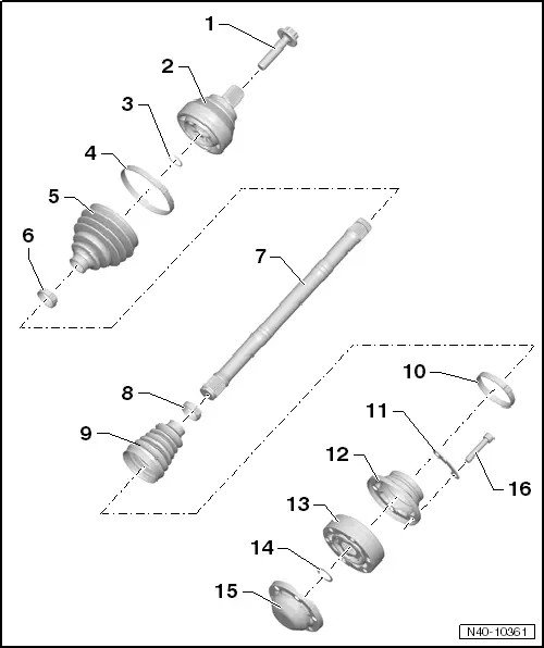
1 - Bolt
- 200 Nm +180º
- Always replace if removed
- Loosening and tightening the twelve-point bolt → Chapter "Drive Axle Threaded Connection, Loosening and Tightening"
- Before installing, clean the threads in the CV joint with a tap.
2 - Outer CV Joint
- When installing the joint on the profile shaft, the splines on the profile shaft must be lightly coated with grease used in joint.
- Checking. Refer to → Chapter "Outer CV Joint, Checking".
- Removing. Refer to → Fig. "Removing the Outer CV Joint".
- Installing.
3 - Locking Ring
- Always replace if removed
- Insert in shaft groove
4 - Clamp
- Always replace if removed
- Tensioning.
5 - CV boot for outer CV joint
- Check for tears and scuffing
6 - Clamp
- Always replace if removed
- Tensioning.
7 - Profile Shaft
8 - Clamp
- Always replace if removed
- Tensioning.
9 - CV Boot for Inner CV Joint
- Check for tears and scuffing
10 - Clamp
- Always replace if removed
- Tensioning.
11 - Locking Plate
12 - Cover
- Always replace if removed
- Drive off CV joint using drift
- Adhesive surface must be free of oil and grease
- Apply sealant between the joint and cover. Refer to → Fig. "Coat the sealing surface on the cover with sealant and then install it.".
13 - Inner CV Joint
- Replace only as complete unit.
- When installing the joint on the profile shaft, the splines on the profile shaft must be lightly coated with grease used in joint.
- Checking. Refer to → Chapter "Inner CV Joint, Checking".
- Removing.
- Installing.
14 - Locking Ring
- Always replace if removed
- Remove and install using Circlip Pliers -VW161A-. Refer to → Fig. "Circlip, Removing and Installing".
15 - Cover
- Always replace if removed
- Drive off CV joint using drift
- Apply sealant between the joint and cover. Refer to → Fig. "Coat the sealing surface on the cover with sealant and then install it.".
16 - Bolt
- Pre-tightening specification: diagonal sequence to 10 Nm.
- M8 tightening specification: diagonal sequence to 40 Nm.
- M10 tightening specification: diagonal sequence to 70 Nm.
- Always replace if removed
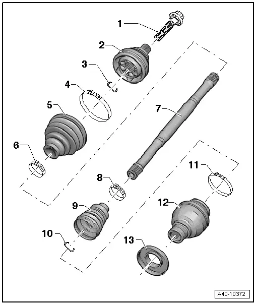
Overview - Drive Axle, Drive Axle with Triple Roller Joint AAR3300i, Mounted in Transmission
1 - Outer CV Joint
- Replace only as complete unit.
- Checking. Refer to → Chapter "Outer CV Joint, Checking".
- Removing.
- Installing: Drive onto shaft with plastic hammer until compressed circlip seats.
2 - Bolt
- 200 Nm +180º
- Always replace if removed
3 - Locking Ring
- Always replace if removed
- Insert in shaft groove
4 - Thrust Ring
- Not installed on all versions
- Installed position.
5 - Plate Spring
- Not installed on all versions
- Installed position.
6 - Clamp
- Always replace if removed
- Tensioning.
7 - CV Boot for CV Joint
- Check for tears and scuffing
- Material: polyelastomer
8 - Clamp
- Always replace if removed
- Tensioning.
9 - Drive Axle
10 - Clamp
- Always replace if removed
- Tensioning.
11 - CV Boot for Triple Roller Joint
- Check for tears and scuffing
12 - Clamp
- Always replace if removed
- Tensioning.
13 - Triple Roller Star with Rollers
The chamfer -arrow- points to drive axle splines.
14 - Locking Ring
- Always replace if removed
- Insert in shaft groove
15 - Joint
16 - Locking Ring
- Always replace if removed
Overview - Drive Axle, Drive Axle with Triple Roller Joint AAR3300i, Mounted on Transmission Stub Shaft
1 - Outer CV joint
- Replace only as complete unit.
- Checking. Refer to → Chapter "Outer CV Joint, Checking".
- Removing. .
- Installing: Drive onto shaft with plastic hammer until compressed circlip seats.
2 - Bolt
- 200 Nm +180º
- Always replace if removed
3 - Locking Ring
- Always replace if removed
- Insert in shaft groove
4 - Clamp
- Always replace if removed
- Tensioning.
5 - CV Boot for CV Joint
- Check for tears and scuffing
- Material: polyelastomer
6 - Clamp
- Always replace if removed
- Tensioning.
7 - Drive Axle
8 - Clamp
- Always replace if removed
- Tensioning.
9 - CV Boot for Triple Roller Joint
- Check for tears and scuffing
10 - Clamp
- Always replace if removed
- Tensioning.
11 - Triple Roller Star with Rollers
The chamfer -arrow- points to drive axle splines.
12 - Locking Ring
- Always replace if removed
- Insert in shaft groove
13 - Adapter
14 - Joint
15 - Cap
- Remove.
- Installing.
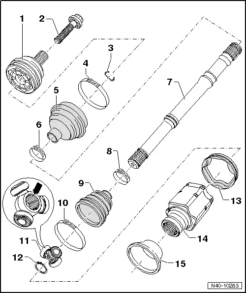
Overview - Drive Axle, Drive Axle with CV Joint, Inserted with Inner Splines
1 - Bolt
- 200 Nm +180º
- Always replace if removed
- Before installing, clean the threads in the CV joint with a tap.
2 - Outer CV Joint
- Replace only as complete unit.
- Divide the grease between the ball paths.
- Checking. Refer to → Chapter "Outer CV Joint, Checking".
- Removing. Refer to → Fig. "Removing Outer CV Joint".
- Installing: Using a plastic hammer, drive onto the shaft as far as the stop
3 - Locking Ring
- Always replace if removed
- Insert in shaft groove
4 - Clamp
- Always replace if removed
- Tensioning.
5 - CV Boot
- Check for tears and scuffing
- Material: polyelastomer
6 - Clamp
- Always replace if removed
- Tensioning.
7 - Drive Axle
8 - Clamp
- Always replace if removed
- Tensioning.
9 - CV Boot for CV Joint
- Check for tears and scuffing
- Material: polyelastomer
10 - Locking Ring
- Always replace if removed
- Insert in shaft groove
11 - Clamp
- Always replace if removed
- Tensioning.
12 - CV Joint
- Replace only as complete unit.
- Divide the grease between the ball paths.
- Removing. Refer to → Fig. "Removing Outer CV Joint".
- Installing: Using a plastic hammer, drive onto the shaft as far as the stop
13 - Protective Cap
- Remove.
- Installing.
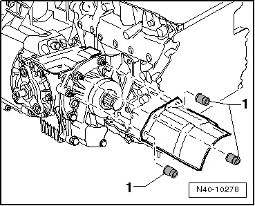
Overview - Drive Axle, Drive Axle Heat Shield
FWD Vehicles:
- Tighten the nuts -arrows- to 35 Nm.
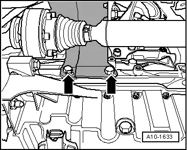
AWD vehicles version 1:
- Tighten the nuts -arrows- to 20 Nm.
AWD vehicles version 2:
- Tighten the nuts -1- to 20 Nm.
READ NEXT:
 Drive Axle, Removing and Installing, Drive Axle with Bolted CV Joint VL
107
Drive Axle, Removing and Installing, Drive Axle with Bolted CV Joint VL
107
Removing
- Loosen the drive axle threaded connection on the wheel side.
Refer to
→ Chapter "Drive Axle Threaded Connection, Loosening and
Tightening".
- Remove the front wheel
Drive Axle, Removing and Installing, Drive Axle with Triple Roller Joint
AAR3300i, Mounted on Transmission Stub Shaft
Special tools and workshop equipment
required
Slide Hammer Set -VW771-
Tensioning Strap -T10038-
Puller - Driveshaft -T10382-
Torque Wrench 1332 40-200Nm -VAG1332-
Digital Torque Wrench
Drive Axle, Removing and Installing, Left Drive Axle with CV Joint, Inserted
with Inner Splines
Special tools and workshop equipment
required
Puller - Driveshaft -T10382-
Torque Wrench 1332 40-200Nm -VAG1332-
Slide Hammer Set -VW771-
Removing
- Loosen the drive axle threaded cSEE MORE:
Emergency assist
Description
Applies to: vehicles with emergency assist
General information
Within the limits of the system, emergency assist
can detect inactivity from the driver. In these instances,
the system will warn the driver, assume
control of the vehicle if necessary, and bring the
vehicle automatically to
Fuel
Types of gasoline
The correct gasoline grade is stated on the inside
of the fuel filler door.
The vehicle is equipped with a catalytic converter
and must only be driven with unleaded gasoline.
Audi recommends using TOP TIER Detergent Gasoline.
For additional information on TOP TIER Detergent
Gasol