Audi Q3: Wheel Bearing Housing, Removing and Installing
Special tools and workshop equipment required
- Puller - Ball Joint -3287A-
- Torque Wrench 1332 40-200Nm -VAG1332-
- Engine and Gearbox Jack -VAS6931-
- Digital Torque Wrench -VAG1756A-
- Spreader Tool -3424-
Removing
- Loosen the drive axle threaded connection on the wheel side. Refer to → Chapter "Drive Axle Threaded Connection, Loosening and Tightening".
- Remove the ABS speed sensor. Refer to → Brake System; Rep. Gr.45; Sensors; Right/Left Front ABS Wheel Speed Sensor G45/G47, Removing and Installing.
- Remove the brake rotor. Refer to → Brake System; Rep. Gr.46; Front Brakes; Brake Rotor, Removing and Installing.
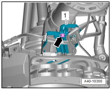
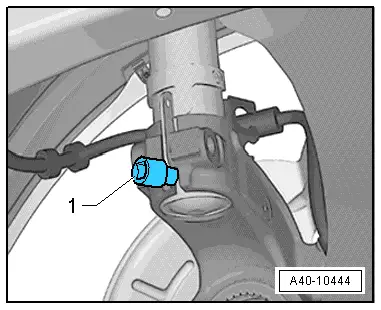
- Remove the bolt -arrow- and remove the bracket -1- for the brake line and wires from the wheel bearing housing.
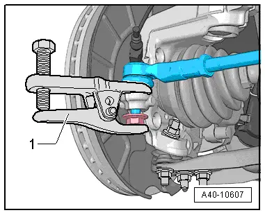
- Loosen nut of track rod ball joint, but do not unscrew yet.
- Press off tie rod end from wheel bearing housing with Puller - Ball Joint -3287A--1- and then remove nut.
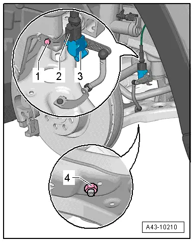
- If installed, remove the nut -4- and free up the coupling rod from the Left Front Level Control System Sensor -G78--3-.
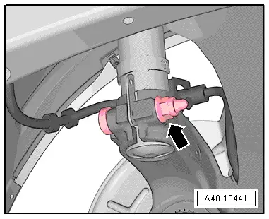
- Disconnect threaded connection of wheel bearing housing/suspension strut -arrow-.
- Insert the Spreader Tool -3424--1- into wheel bearing housing slot.
- Turn the ratchet 90º and remove it from the Spreader Tool -3424--1-.
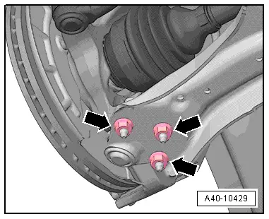
- Remove the nuts -arrows-.
- Remove the control arm out of wheel bearing housing with ball joint.
 Note
Note
Pay attention during the assembly work that the ball joint rubber boot is not damaged. If necessary protect the ball joint rubber boot against damage.
- Remove the wheel bearing housing downward from the shock absorber tube and remove the drive axle from the wheel hub.
 Note
Note
- The drive axle must not hang down, otherwise the inner joint will be damaged by overflexing.
- Secure drive axle to body using wire.
- Remove the wheel bearing housing with ball joint.
Installing
Install in reverse order of removal while noting the following:
- Install the brake caliper. Refer to → Brake System; Rep. Gr.46; Front Brakes; Brake Caliper, Removing and Installing.
- Tighten the twelve-point bolt on the driveshaft. Refer to → Chapter "Drive Axle Threaded Connection, Loosening and Tightening".
- An axle alignment may be required. Refer to → Chapter "Evaluating Need for Axle Alignment".
- On vehicles with electronically controlled damping, perform the function "Adapt the control position" with the Vehicle Diagnosis Tester.
- If the control position was reprogrammed and if the vehicle has lane assist, then it will then be necessary to calibrate the driver assistance systems front camera. Refer to → Chapter "Driver Assistance Systems Front Camera, Calibrating".
- On vehicles with level control system sensor, perform headlamp basic setting. Refer to → Electrical Equipment; Rep. Gr.94; Headlamp, Adjusting.
Tightening Specifications
- Brake rotor.
READ NEXT:
 Wheel Bearing Unit, Removing and Installing
Special tools and workshop equipment
required
Torque Wrench 1332 40-200Nm -VAG1332-
Removing
- Loosen the drive axle threaded connection on the wheel side.
Refer to
→ Chapter
Overview - Drive Axle
Overview - Drive Axle, Drive Axle with CV Joint VL107
1 - Bolt
200 Nm +180º
Always replace if removed
Loosening and tightening the twelve-point bolt
→ Chapter "Drive Axl
Drive Axle, Removing and Installing, Drive Axle with Bolted CV Joint VL
107
Removing
- Loosen the drive axle threaded connection on the wheel side.
Refer to
→ Chapter "Drive Axle Threaded Connection, Loosening and
Tightening".
- Remove the front wheelSEE MORE:
Unlocking and locking the vehicle
Fig. 26 Door handle: sensor for locking the vehicle
Depending on the vehicle equipment, you may
have various options for unlocking and locking
your vehicle. The settings in the MMI specify
which doors will unlock.
Unlocking or locking using the vehicle key
buttons
To unlock the vehicle, press the
Additional safety belt functions
Belt retractor lock
The safety belts on the rear seats and on the
front passenger seat are equipped with a belt retractor
lock.
If you secure a child safety seat with a safety
belt, the belt retractor lock on the safety belt
may need to be activated. Follow the instructions
from the child safet