
Audi Q3: Overview - Transverse Link
Suspension, Wheels, Steering / Chassis / Audi Q3 (8U) 2011-2018 Service Manual / Overview - Transverse Link
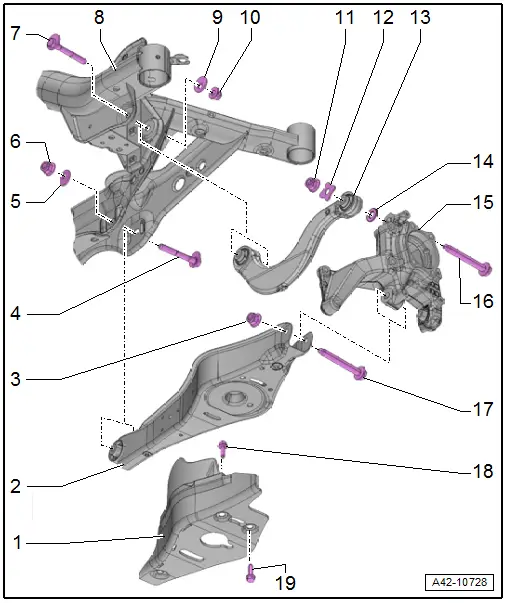
1 - Stone Chip Protection
- For allocation. Refer to the Parts Catalog.
2 - Lower Transverse Link
- Removing and installing. Refer to → Chapter "Lower Transverse Link, Removing and Installing, FWD Vehicles".
3 - Nut
- 90 Nm + 90º
- Always replace if removed
- Always tighten threaded connections in curb weight position. Refer to → Chapter "Wheel Bearing in Curb Weight, Lifting Vehicles with Coil Spring".
4 - Eccentric Screw
- Do not turn more than 90º right or left (that is smallest to largest possible adjustment)
- For toe setting
- Perform a vehicle alignment after loosening. Refer to → Chapter "Axle Alignment Procedure".
5 - Eccentric Washer
- Inner bore with tab
6 - Nut
- 95 Nm
- Always replace if removed
- Always tighten threaded connections in curb weight position. Refer to → Chapter "Wheel Bearing in Curb Weight, Lifting Vehicles with Coil Spring".
7 - Eccentric Screw
- Do not turn more than 90º right or left (that is smallest to largest possible adjustment)
- For camber setting
- Perform a vehicle alignment after loosening. Refer to → Chapter "Axle Alignment Procedure".
8 - Subframe
- Removing and installing. Refer to → Chapter "Subframe, Removing and installing, FWD Vehicles".
9 - Eccentric Washer
- Inner bore with tab
10 - Nut
- 95 Nm
- 80 Nm. This tightening specification only applies in conjunction with Insert Tool - 18mm -T10179-
- Always replace if removed
- Always tighten threaded connections in curb weight position. Refer to → Chapter "Wheel Bearing in Curb Weight, Lifting Vehicles with Coil Spring".
11 - Nut
- For tightening specifications, see bolt -16-
- Always replace if removed
12 - Washer
13 - Upper Transverse Link
- Removing and installing. Refer to → Chapter "Upper Transverse Link, Removing and Installing, FWD Vehicles".
14 - Washer
15 - Wheel Bearing Housing
16 - Bolt
- 130 Nm + 90º
- Always replace if removed
- Always tighten threaded connections in curb weight position. Refer to → Chapter "Wheel Bearing in Curb Weight, Lifting Vehicles with Coil Spring".
17 - Bolt
- Always replace if removed
18 - Expanding Rivet
- Quantity: 2
19 - Bolt
- 8 Nm
- Quantity: 3
Overview - Tie Rod
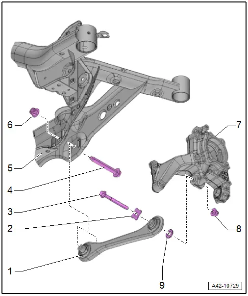
1 - Tie Rod
- Removing and installing. Refer to → Chapter "Tie Rod, Removing and Installing, FWD Vehicles".
2 - Washer
3 - Bolt
- 130 Nm + 90º
- Always replace if removed
- Always tighten threaded connections in curb weight position. Refer to → Chapter "Wheel Bearing in Curb Weight, Lifting Vehicles with Coil Spring".
4 - Bolt
- Always replace if removed
5 - Subframe
- Removing and installing. Refer to → Chapter "Subframe, Removing and installing, FWD Vehicles".
6 - Nut
- 90 Nm + 90º
- Always replace if removed
7 - Wheel Bearing Housing
8 - Nut
- Always replace if removed
9 - Washer
READ NEXT:
 Upper Transverse Link, Removing and Installing
Upper Transverse Link, Removing and Installing, FWD Vehicles
Special tools and workshop equipment
required
Torque Wrench 1332 40-200Nm -VAG1332-
Removing
- Measure dimension from cente
Lower Transverse Link, Removing and Installing
Lower Transverse Link, Removing and Installing, FWD Vehicles
Special tools and workshop equipment
required
Torque Wrench 1332 40-200Nm -VAG1332-
Removing
- Measure dimension from cente
Tie Rod, Removing and Installing
Tie Rod, Removing and Installing, FWD Vehicles
Special tools and workshop equipment
required
Torque Wrench 1331 5-50Nm -VAG1331-
Torque Wrench 1332 40-200Nm -VAG1332-
Removing
- MeasSEE MORE:
Overview - Interior Rearview Mirror
Overview - Interior Rearview Mirror, Version 1
1 - Front Cover
For the mirror base
Removing and installing. Refer to
→ Chapter "Interior Rearview Mirror, Removing and Installing".
2 - Clip
For the interior rearview mirror
There are different versions. R
Front Exterior Door Handle Switch, Removing and Installing
Removing
- Remove the exterior door handle. Refer to
→ Body Exterior; Rep. Gr.57; Door Components; Door Handle,
Removing and Installing.
Note
Ignore -1 and 2-.
- Release the retaining tabs in direction of
-A arrows- and remove the connector
-3-.
- C
© 2019-2026 Copyright www.auq3.net | 0.0103
