Audi Q3: Tie Rod, Removing and Installing
Tie Rod, Removing and Installing, FWD Vehicles
Special tools and workshop equipment required
- Torque Wrench 1331 5-50Nm -VAG1331-
- Torque Wrench 1332 40-200Nm -VAG1332-
Removing
- Measure dimension from center of wheel to lower edge of wheel housing. Refer to → Chapter "Wheel Bearing in Curb Weight, Lifting Vehicles with Coil Spring".
- Remove the affected rear wheel. Refer to → Chapter "Wheels and Tires".
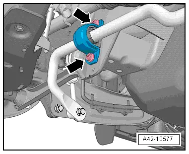
- Remove the nut -1- and pull the coupling rod -2- out of the stabilizer bar.
- Remove the bolts -arrows- for the stabilizer bar clamp. Refer to → Chapter "Stabilizer Bar, Removing and Installing".

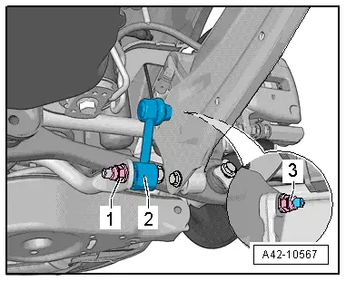
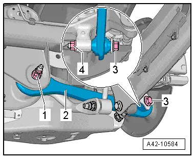
- Remove the nut -4- and bolt -3-.
- Remove the nut -1- and then remove the bolt to the rear.
- Remove the tie rod -2-.

Installing
Installation is reverse of removal, noting the following:
- The tie rod may only be fastened when the dimension between wheel hub center and lower edge of wheel housing, measured before assembly, is achieved. Refer to → Chapter "Wheel Bearing in Curb Weight, Lifting Vehicles with Coil Spring".
- An axle alignment may be required. Refer to → Chapter "Evaluating Need for Axle Alignment".
Tie Rod, Removing and Installing, AWD Vehicles
Special tools and workshop equipment required
- Torque Wrench 1331 5-50Nm -VAG1331-
- Torque Wrench 1332 40-200Nm -VAG1332-
Removing
- Measure dimension from center of wheel to lower edge of wheel housing. Refer to → Chapter "Wheel Bearing in Curb Weight, Lifting Vehicles with Coil Spring".
- Remove the affected rear wheel. Refer to → Chapter "Wheels and Tires".
- Remove the nut -1- and pull the coupling rod -2- out of the stabilizer bar.

- Remove the bolts -arrows- for the stabilizer bar clamp.
- Remove the nut -4- and bolt -3-.
- Remove the nut -1- and then remove the bolt to the rear.
- Remove the bolt -2-.
Installing
Installation is reverse of removal, noting the following:
- The control arm may only be fastened if the dimension between the wheel hub center and lower edge of wheel housing, measured before assembly, is achieved. Refer to → Chapter "Wheel Bearing in Curb Weight, Lifting Vehicles with Coil Spring".
- Install the coil spring. Refer to → Chapter "Spring, Removing and Installing".
- An axle alignment may be required. Refer to → Chapter "Evaluating Need for Axle Alignment".
READ NEXT:
 Suspension Strut/Shock Absorber, Spring
Overview - Suspension Strut, Shock Absorber and Spring
1 - Lower Spring Support
Spring end rotated up to stop
2 - Coil Spring
Removing and installing. Refer to
→&
Overview - Wheel Bearing
Overview - Wheel Bearing, Vehicles with FWD
1 - Cover
2 - Bracket
3 - Bolt
50 Nm + 45º
Always replace if removed
4 - Coupling Rod
5 -
Wheel Bearing Housing, Removing and Installing
Wheel Bearing Housing, Removing and Installing, FWD Vehicles
Special tools and workshop equipment
required
Torque Wrench 1332 40-200Nm -VAG1332-
Removing
- Measure dimension from centeSEE MORE:
Water Drain Hoses
Overview - Water Drain Hoses
1 - Front Water Drain Hose
Removing and installing. Refer to
→ Chapter "Water Drain Hoses, Removing and Installing".
Cleaning, refer to
→ Chapter "Water Drain Hoses, Cleaning"
2 - Panorama Sunroof
3 - Rear Wate
Instrument Panel Central Tube
Overview - Instrument Panel Central Tube
1 - Bolt
20 Nm
2 - Nut
23 Nm
Quantity: 2
Always replace if removed
3 - Threaded Pin
20 Nm
Quantity: 2
4 - Balancing Element
Clip in on the central tube
Check the balanc