Audi Q3: Overview - Subframe
Suspension, Wheels, Steering / Chassis / Audi Q3 (8U) 2011-2018 Service Manual / Overview - Subframe
 Caution
There is a risk of damaging the subframe threaded connection threads on the body.
- The subframe bolts on the body must not be loosened or tightened with an impact wrench.
- Always install all bolts by hand for the first few turns.
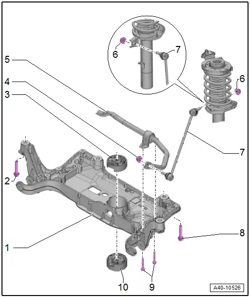
1 - Subframe
- Securing. Refer to → Chapter "Subframe, Securing".
- Lowering. Refer to → Chapter "Subframe, Lowering".
- Removing and installing without steering gear. Refer to → Chapter "Subframe without Steering Gear, Removing and Installing".
- Removing and installing with steering gear. Refer to → Chapter "Subframe with Steering Gear, Removing and Installing".
2 - Bolt
- 70 Nm +180º
- Always replace if removed
3 - Upper Bonded Rubber Bushing for Pendulum Support
- Replacing. Refer to → Chapter "Subframe, Servicing".
4 - Nut
- 65 Nm
- Always replace if removed
- Counterhold at socket head of joint bolt when tightening
5 - Stabilizer Bar
- Removing and installing. Refer to → Chapter "Stabilizer Bar, Removing and Installing".
6 - Nut
- 65 Nm
- Always replace if removed
- Counterhold at socket head of joint bolt when tightening
7 - Coupling Rod
- Removing and installing. Refer to → Chapter "Coupling Rod, Removing and Installing".
8 - Bolt
- 70 Nm +180º
- Always replace if removed
9 - Bolts
- 20 Nm +90º
- Always replace if removed
10 - Lower Bonded Rubber Bushing for Pendulum Support
- Replacing. Refer to → Chapter "Subframe, Servicing".
READ NEXT:
 Subframe without Steering Gear, Removing and Installing
Special tools and workshop equipment
required
Torque Wrench 1331 5-50Nm -VAG1331-
Torque Wrench 1332 40-200Nm -VAG1332-
Engine and Gearbox Jack -VAS6931-
Removing
Note
Subframe
Subframe, Servicing
Special tools and workshop equipment
required
Bearing Installer - Wheel Hub/Bearing Kit -T10205-
Torque Wrench 1332 40-200Nm -VAG1332-
Hydraulic Press -VAS6178-
Pneumatic/Hydraulic Foot Pu
Stabilizer Bar, Removing and Installing
Special tools and workshop equipment
required
Locating Pins -T10096-
Torque Wrench 1332 40-200Nm -VAG1332-
Engine and Gearbox Jack -VAS6931-
Puller - Ball Joint -3287A-
Removing
- SEE MORE:
Engine oil temperature indicator
Applies to: vehicles with engine oil temperature indicator
Depending on the vehicle equipment, the engine
oil temperature may be indicated by
a bar in
the instrument cluster.
Open the vehicle functions tab.
When engine oil temperatures are low, the display
--- ºF (--- ºC) appears in the instr
Center Grille. Removing and Installing, Audi Q3 Offroad
Removing
- Remove the noise insulation. Refer to
→ Chapter "Overview - Noise Insulation".
- Remove the front bumper cover end plate. Refer to
→ Chapter "Front Bumper Cover End Plate, Removing and
Installing".
- Remove the bolts -arrows-.
- Disconnect the co
© 2019-2026 Copyright www.auq3.net | 0.0101
