Audi Q3: Stabilizer Bar, Removing and Installing
Special tools and workshop equipment required
- Locating Pins -T10096-
- Torque Wrench 1332 40-200Nm -VAG1332-
- Engine and Gearbox Jack -VAS6931-
- Puller - Ball Joint -3287A-
Removing
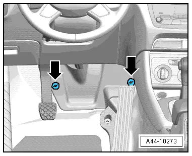
- Remove the footwell trim panel by removing the nuts -arrows-.
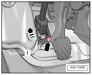
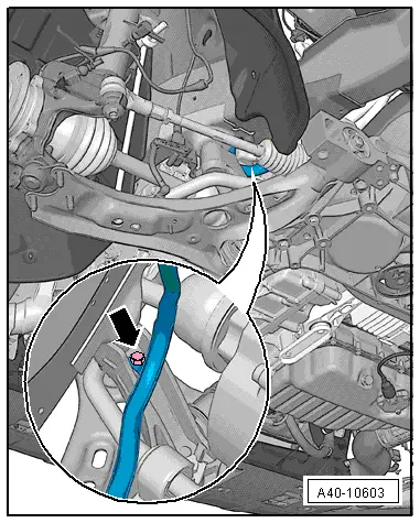
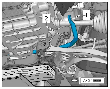
- Remove the bolt -arrow- from the universal joint -1-. Then remove the universal joint from the steering gear in direction of -arrow-.
- Remove the front wheels. Refer to → Chapter "Wheels and Tires".
- Secure the subframe. Refer to → Chapter "Subframe, Securing".
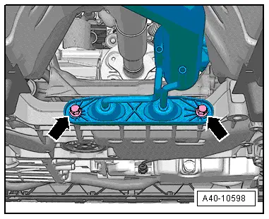
- Remove the bolts -arrows-.
- If installed, remove the Left Front Level Control System Sensor -G78- or Right Front Level Control Sensor -G289-. Refer to → Chapter "Left/Right Front Level Control System Sensor -G78-/-G289-, Removing and Installing".
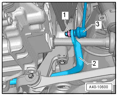
- Remove the left and right nut -1- from the coupling rod -3-.
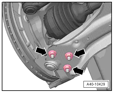
- Remove the nuts -arrows-.
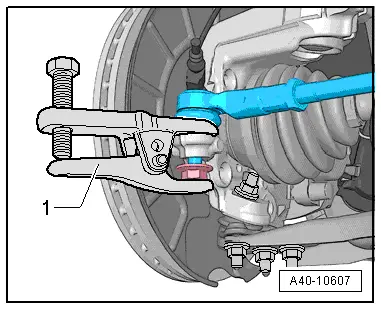
- Loosen the nut of the tie rod end, but do not remove yet.
- Remove the tie rod end from the wheel bearing housing using the Puller - Ball Joint -3287A--1-.
- Remove the stabilizer bar from the subframe by removing the bolts -1 and 4-.
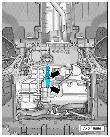
- Remove the bolts -arrows- and then remove the pendulum support from the transmission.
Vehicles with 4-cylinder Engine
- Disconnect the connector for the Oil Level Thermal Sensor -G266--arrow- and free up the wire.
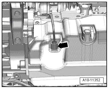
Continuation for All Vehicles
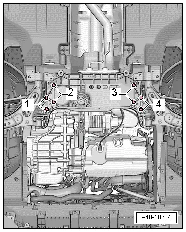
- Loosen the bolts -1- and -2- to slightly lower the subframe. Pay attention the electrical wiring while doing this.
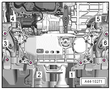
- Remove the cable guide from the subframe -arrow-.
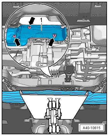
- Lower the subframe until the bolted connections -arrows- on the steering gear heat shield -1- are accessible.
- Remove the bolts -arrows- and the heat shield -1-.
- Slide the stabilizer bar toward the right, as seen in direction of travel.
- Remove the stabilizer bar -1- forward from the subframe over the console -2-.
Installing
Install in reverse order of removal while noting the following:
- Remove the Locating Pins -T10096-.
- Install the subframe with the steering gear. Refer to → Chapter "Subframe with Steering Gear, Removing and Installing".
- Install the front wheels. Refer to → Chapter "Wheels and Tires".
- An axle alignment may be required. Refer to → Chapter "Evaluating Need for Axle Alignment".
Tightening Specifications
- Pendulum support.
- Exhaust system bracket.
Coupling Rod, Removing and Installing
Special tools and workshop equipment required
- Torque Wrench 1331 5-50Nm -VAG1331-
- Torque Wrench 1331 Insert - Ring Wrench - 16mm -VAG1331/12-
Removing
- Remove the front wheel. Refer to → Chapter "Wheels and Tires".
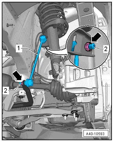
- Remove the nuts -arrows- from the coupling rod -1- by counterholding with a multipoint socket on the threaded pin -2- if necessary.
- Remove the coupling rod -1- from the stabilizer bar and suspension strut.
- Remove the coupling rod -1-.
Installing
Installation is reverse of removal, noting the following:
- Tighten the nuts -arrow- for securing the coupling rod on the suspension strut or stabilizer bar by counterholding with a multipoint socket on the threaded pin -2-.
 Note
Note
The counter hold tool cannot be tilted.
- Install the front wheel.
READ NEXT:
 Subframe, Securing
Special tools and workshop equipment
required
Locating Pins -T10096-
Torque Wrench 1332 40-200Nm -VAG1332-
Engine and Gearbox Jack -VAS6931-
Procedure
- Remove the noise insulation
Suspension Strut and Upper Control Arm
Overview - Suspension Strut and Upper Control Arm
1 - Shock Absorber
On vehicles with electronically controlled damping, perform the
function "Adapt the control position" with the V
Overview - Lower Control Arm and Ball Joint
1 - Control Arm
Control arm with mounting bracket, removing and installing. Refer to
→ Chapter "Lower Control Arm, Removing and Installing".
2 - Bonded Rubber BushSEE MORE:
Airbag system
General information
WARNING
If you have not fastened your safety belt,
you are in an incorrect seating position, or
you are too close to the airbag system, the
airbag system will not be able to protect
you. This increases the risk of serious or fatal
injuries. Make sure that every vehicle
pa
Steering wheel heating
Switching on and off
Applies to: vehicles with steering wheel heating
Press the button on the
multifunction steering
wheel to switch the steering wheel heating
on and off.
Messages
Applies to: vehicles with steering wheel heating
The following messages may appear depending
on the vehicle equ