Audi Q3: Instrument Cluster
Overview - Instrument Cluster
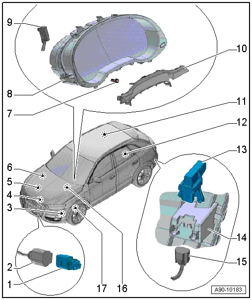
1 - Outside Air Temperature Sensor -G17-
- Removing and installing. Refer to → Chapter "Outside Air Temperature Sensor, Removing and Installing".
2 - Connector
- For Outside Air Temperature Sensor -G17-
3 - Windshield Washer Fluid Level Sensor -G33-
- Removing and installing. Refer to → Chapter "Windshield Washer Fluid Level Sensor, Removing and Installing".
4 - Oil Level Thermal Sensor -G266-
- Removing and installing. Refer to → Rep. Gr.17; Oil Pan/Oil Pump; Oil Level Thermal SensorG266, Removing and Installing.
5 - Oil Pressure Switch
- Removing and installing. Refer to → Rep. Gr.17; Oil Filter/Oil Pressure Switch.
6 - Engine Coolant Level Warning Switch -F66-
7 - Bolt
- 3 Nm
- Quantity: 2
8 - Instrument Cluster
- With Instrument Cluster Control Module -J285-
- Removing and installing. Refer to → Chapter "Instrument Cluster with Instrument Cluster Control Module -J285-, Removing and Installing".
- Multi-pin connector pin assignment. Refer to → Chapter "Instrument Cluster Multi-Pin Connector Contact Assignment".
9 - Connector
- For instrument cluster
10 - Gap Cover
- Removing and Installing. Refer to → Body Interior; Rep. Gr.68; Storage Compartments/Covers; Instrument Cluster Gap Cover, Removing and Installing.
11 - Fuel Level Sensor -G-
- Connector assignment. Refer to → Chapter "Fuel Level Sensor -G- Connector Assignment".
- Removing and Installing. Refer to → Rep. Gr.20; Fuel Delivery Unit/Fuel Level Sensor; Fuel Level SensorG Removing and Installing.
12 - Fuel Level Sensor 2 -G169-
- Connector assignment. Refer to → Chapter "Fuel Level Sensor 2 -G169- Connector Assignment".
- Removing and installing. Refer to → Fuel Supply System; Rep. Gr.20; Fuel Delivery Unit/Fuel Level Sensor; Fuel Level Sensor 2G169, Removing and Installing
13 - Radio Frequency Controlled Clock Receiver -J489-
- Removing and installing. Refer to → Chapter "Radio Frequency Controlled Clock Receiver, Removing and Installing".
14 - Mount
- Integrated in the bumper cover
15 - Connector
- For Radio Frequency Controlled Clock Receiver -J489-
16 - Brake Fluid Level Warning Switch -F34-
- Removing and Installing. Refer to → Break System; Rep. Gr.47; Overview - Brake Booster/Brake Master Cylinder.
17 - Left Front Brake Pad Wear Sensor -G34-
- Removing and installing. Refer to → Brake System; Rep. Gr.46; Front Brakes; Brake Pads, Removing and Installing.
Instrument Cluster with Instrument Cluster Control Module -J285-, Removing and Installing
Special tools and workshop equipment required
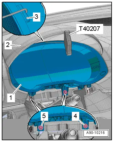
- Hook Tool -T40207-
 Note
Note
- All warning lamps in instrument cluster are fitted with light-emitting diodes. Instrument cluster must be replaced in the event of warning lamp failure.
- Do not disassemble the instrument cluster.
- It is not necessary to remove the steering wheel in order to remove the instrument cluster.
- If replacing the control module, select the "Replace Control Module" function Vehicle Diagnostic Tester.
Removing
- Adjust steering wheel downward and to rear as far as possible, use entire adjustment range of steering column adjustment for this.
- Turn off the ignition.
- Vehicles with ignition lock: Remove the key.
- Remove the gap cover and place on the upper steering column trim panel. Refer to → Body Interior; Rep. Gr.68; Storage Compartments/Covers; Instrument Cluster Gap Cover, Removing and Installing.
- Remove the bolts -4 and 5-.
- Guide the Hook Tool -T40207- carefully between the instrument panel -2- and the instrument cluster -1- and engage from behind in the pull tab -3-.
- Pull the instrument cluster out just far enough until it is touching the steering wheel.
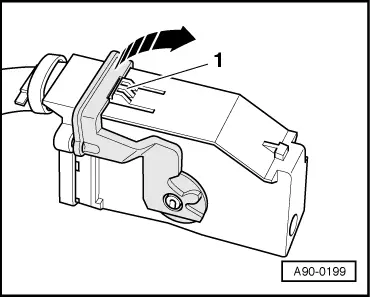
- Disconnect the connector.
- To disconnect the connector, press the tab -1-, turn the retaining bracket in direction of -arrow- and remove the connector.
- Remove the instrument cluster on the driver side between the steering wheel and the instrument panel.
Installing
Install in reverse order of removal. Note the following:
- Follow the instructions on the Vehicle Diagnostic Tester display with a new instrument cluster.
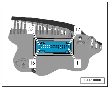
Instrument Cluster Multi-Pin Connector Contact Assignment
32-Pin Connector, Gray
1 - Fuel Level Sensor -G- - full
2 - Fuel Level Sensor -G- - empty
3 - Fuel Level Sensor 2 -G169- - full
4 - Fuel Level Sensor 2 -G169- - empty
5 - Radio controlled clock signal
6 - Radio Frequency Controlled Clock 5 V
7 - Transponder 1
8 - Transponder 2
9 - Not Assigned
10 - Not Assigned
11 - Oil Level Thermal Sensor -G266-
12 - Not Assigned
13 - Not Assigned
14 - Not Assigned
15 - Brake pad
16 - Terminal 31
17 - Windshield Washer Fluid Level Sensor -G33-
18 - Engine Coolant Level Warning Switch -F66-
19 - Outside Air Temperature Sensor -G17-
20 - Sensor ground
21 - Not Assigned
22 - Not Assigned
23 - Not Assigned
24 - Not Assigned
25 - Electromechanical Parking Brake Control Module -J540- signal
26 - Brake Fluid Level Warning Switch -F34-
27 - Oil pressure
28 - Instrument cluster CAN bus High
29 - Instrument cluster CAN bus Low
30 - Not Assigned
31 - Not Assigned
32 - Terminal 30
READ NEXT:
 Fuel Level Sensor Connector Assignment
Fuel Level Sensor -G- Connector Assignment
Disconnect the connector on the fuel tank locking flange.
For the procedure. Refer to
→ Rep. Gr.20; Fuel Delivery Unit/Fuel Level Sensor; Fu
Horn
Overview - Horn
1 - Nut
9 Nm
2 - Nut
9 Nm
3 - Low Tone Horn -H7-
Removing and installing. Refer to
→ Chapter "High Tone Horn -H2-/Low Tone HSEE MORE:
Front seats
General information
Make sure that:
You can press the pedals down completely
while your legs are slightly bent.
The distance between your upper body and the
steering wheel or instrument panel is at least
10 inches (25 cm).
The distance between your knees and the instrument
panel is at least
Checking coolant
Fig. 150 Engine compartment - coolant expansion tank (diagram): 1 cover; 2
markings
Observe the safety precautions.
Checking the coolant level
Park the vehicle on a level surface.
Switch the ignition off.
Open the hood.
Check the coolant level in the coolant expansion
tank fig. 146 using th