Audi Q3: Fuel Level Sensor Connector Assignment
Fuel Level Sensor -G- Connector Assignment
Disconnect the connector on the fuel tank locking flange. For the procedure. Refer to → Rep. Gr.20; Fuel Delivery Unit/Fuel Level Sensor; Fuel Delivery Unit/Fuel Level Sensor Assembly Overview.
 Note
Note
Check the exact assignment in the current wiring diagram. Refer to → Wiring diagrams, Troubleshooting & Component locations.
Fuel Level Sensor 2 -G169- Connector Assignment
Disconnect the connector on the fuel tank locking flange. For the procedure. Refer to → Rep. Gr.20; Fuel Delivery Unit/Fuel Level Sensor; Fuel Level Sensor 2G169, Checking.
 Note
Note
Check the exact assignment in the current wiring diagram. Refer to → Wiring diagrams, Troubleshooting & Component locations.
Engine Coolant Temperature Sensor Connector Assignment
Engine Coolant Temperature Sensor -G62- Connector Assignment
Disconnect the connector on the Engine Coolant Temperature Sensor -G62-. Procedure. Refer to → Rep. Gr.19; Coolant Pump/Coolant Regulation.
 Note
Note
Check the exact assignment in the current wiring diagram. Refer to → Wiring diagrams, Troubleshooting & Component locations.
Engine Coolant Temperature Sensor on Radiator Outlet -G83- Connector Assignment - TDI-Engines
Disconnect the connector on the Engine Coolant Temperature Sensor On Radiator Outlet -G83-. For the procedure. Refer to → Rep. Gr.19; Coolant Pump/Thermostat - the sensor is not removed.
 Note
Note
Check the exact assignment in the current wiring diagram. Refer to → Wiring diagrams, Troubleshooting & Component locations.
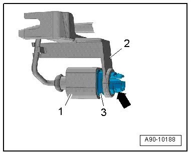
Outside Air Temperature Sensor, Removing and Installing
Removing
- Reach through the opening on the radiator grille and carefully push the retaining tabs together -arrow-, while doing so remove the Outside Air Temperature Sensor -G17--3- from the bracket -2-.
- Disconnect the connector -1-.
Installing
Install in reverse order of removal.
Clock
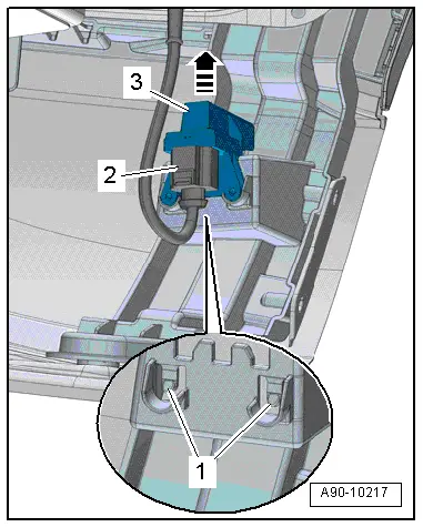
Radio Frequency Controlled Clock Receiver, Removing and Installing
Removing
- Disconnect the connector -2- on the Radio Frequency Controlled Clock Receiver -J489-.
- Carefully push the retaining clips -1- rearward and at the same time remove the Radio Frequency Controlled Clock Receiver -J489--3- upward from the mount in direction of -arrow-.
Installing
Install in reverse order of removal. Note the following:
- Push the Radio Frequency Controlled Clock Receiver -J489- until it audibly locks in the mount.
READ NEXT:
 Horn
Horn
Overview - Horn
1 - Nut
9 Nm
2 - Nut
9 Nm
3 - Low Tone Horn -H7-
Removing and installing. Refer to
→ Chapter "High Tone Horn -H2-/Low Tone H
Windshield Wiper System
Overview - Windshield Wiper System
Overview - Windshield Wiper System
1 - Bolt
Tightening sequence. Refer to → Fig. " Windshield Wiper
Motor -V- - Tightening Specification SEE MORE:
Turn signal and high beam lever
Fig. 38 Operating lever: switching the light functions on
and off
The lever operates the turn signals, the high
beams and the headlight flasher.
Turn signals
The turn signal will activate when you move the
lever into a turn signal position while the ignition
is switched on. The respective or
ind
Refueling
Messages
The following messages may appear depending
on the vehicle equipment:
Messages
If the indicator light appears
with a corresponding
message, refuel the vehicle.
Tank system: malfunction!
Please contact
Service
There is a malfunction in the fuel tank system.
Drive to an authorized Audi d