Audi Q3: Component Location Overview - Instrument Panel
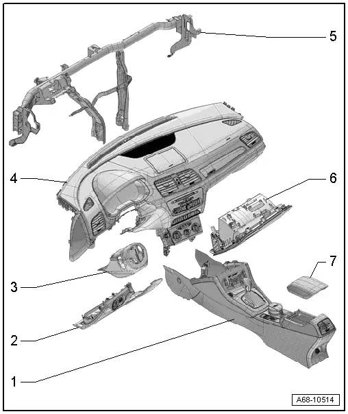
1 - Center Console
- Overview. Refer to → Chapter "Overview - Center Console".
2 - Driver Side Instrument Panel Cover
- Overview. Refer to → Chapter "Overview - Driver Side Instrument Panel Cover".
3 - Trim Panel
- For the steering column switch module
- Overview. Refer to → Chapter "Overview - Steering Column Trim Panel".
4 - Instrument Panel
 WARNING
Follow all safety precautions when working with pyrotechnic components. Refer to → Chapter "Pyrotechnic Components Safety Precautions".
- Overview. Refer to → Chapter "Overview - Instrument Panel".
5 - Central Tube
- For the instrument panel
- Overview. Refer to → Chapter "Overview - Instrument Panel Central Tube".
6 - Glove Compartment
- Overview. Refer to → Chapter "Overview - Glove Compartment".
7 - Front Center Armrest
- Overview. Refer to → Chapter "Overview - Front Center Armrest".
Overview - Instrument Panel
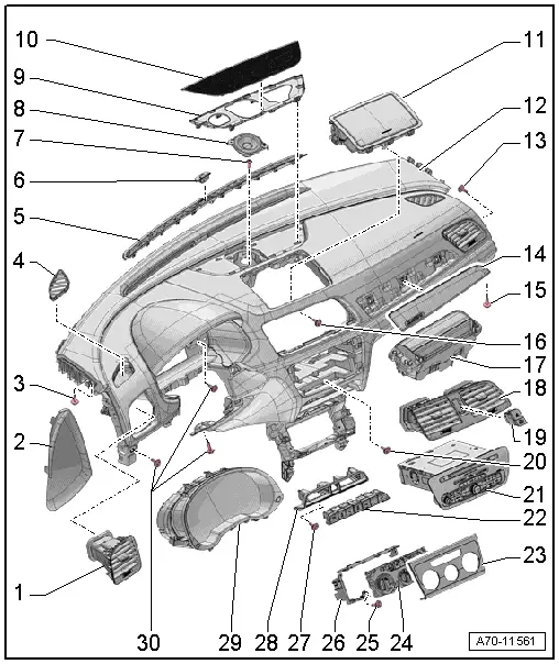
1 - Side Instrument Panel Vent
- Removing and installing. Refer to → Chapter "Side Instrument Panel Vent, Removing and Installing".
- Replace damaged or deformed clips
- When sliding it into the installation opening, make sure the air duct engages correctly.
- Press it into the installation opening as far as the stop.
2 - Side Cover
- For the instrument panel
- Removing and installing. Refer to → Chapter "Instrument Panel Side Cover, Removing and Installing".
- Press on until it engages audibly
3 - Bolt
- 3 Nm
4 - Side Defroster Vent
- Removing and installing. Refer to → Chapter "Side Defroster Vent, Removing and Installing".
- Press on it until it locks
5 - Defroster Vent in the Center
- Removing and installing. Refer to → Chapter "Front Center Defroster Vent, Removing and Installing".
- Press on it until it locks
6 - Sunlight Photo Sensor -G107-
- Removing and installing. Refer to → Heating, Ventilation, and Air Conditioning; Rep. Gr.87; Additional Components for Control and Regulation; Sunlight Photo SensorG107 Removing and Installing.
7 - Bolt
- 3 Nm
8 - Center Speaker -R208-
- Equipment levels
- Removing and installing. Refer to → Communication; Rep. Gr.91; Sound System; Component Location Overview - Sound System.
9 - Mount
- For the speaker trim
- Removing and installing. Refer to → Chapter "Speaker Trim Mount, Removing and Installing".
- Replace damaged or deformed clips
- Press on it until it locks
10 - Center Speaker Trim
- Removing and installing. Refer to → Chapter "Speaker Trim, Removing and Installing".
- First, insert in the front of the instrument panel and press on it until it engages audibly.
11 - Front Information Display Control Head -J685-/Storage Compartment
- Equipment levels
- Removing and installing the front information display control head -J685-. Refer to → Communication; Rep. Gr.91; Infotainment System; Component Location Overview - Infotainment System.
- Removing and installing the storage compartment. Refer to → Chapter "Instrument Panel Storage Compartment, Removing and Installing".
- Insert in the front of the instrument panel and press on it until it engages audibly.
12 - Instrument Panel
 WARNING
- Follow all safety precautions when working with pyrotechnic components. Refer to → Chapter "Pyrotechnic Components Safety Precautions".
- Follow the allocation of the airbag to the instrument panel. Refer to the Parts Catalog.
- Removing and installing. Refer to → Chapter "Instrument Panel, Removing and Installing".
13 - Bolt
- 3 Nm
14 - Front Passenger Side Trim
- For the instrument panel
- Clipped in the instrument panel
- Removing and installing. Refer to → Chapter "Instrument Panel Decorative Trim, Removing and Installing".
- Press on until it engages audibly
15 - Bolt
- 3 Nm
16 - Bolt
- 3 Nm
17 - Front Passenger Airbag
- With Front Passenger Airbag Igniter 1 -N131-
 WARNING
- Follow all safety precautions when working with pyrotechnic components. Refer to → Chapter "Pyrotechnic Components Safety Precautions".
- Follow the allocation of the airbag to the instrument panel. Refer to the Parts Catalog.
- Overview. Refer to → Chapter "Overview - Front Passenger Airbag".
- Removing and installing. Refer to → Chapter "Front Passenger Airbag Unit with Igniter, Removing and Installing".
18 - Center Instrument Panel Vent
- Removing and installing. Refer to → Chapter "Center Instrument Panel Vent, Removing and Installing".
- Replace damaged or deformed clips
- When sliding it into the installation opening, make sure the air duct engages correctly.
- Press it into the installation opening as far as the stop.
19 - Switch Unit
- With Front Passenger Airbag -Disabled- Indicator Lamp -K145-, Emergency Flasher Button -E229-
- Removing and Installing. Refer to → Electrical Equipment; Rep. Gr.96; Controls; Component Location Overview - Controls in the Instrument Panel.
20 - Bolt
- 3 Nm
21 - Radio -R-/Navigation System
- Equipment levels
- Removing and installing. Refer to → Communication; Rep. Gr.91; Component Location Overview - Navigation System.
22 - Lower Button Unit
- Removing and Installing. Refer to → Electrical Equipment; Rep. Gr.96; Controls; Component Location Overview - Controls in the Instrument Panel.
23 - Trim
- Only for A/C Control Module -J301-
- Removing and installing. Refer to → Heating, Ventilation and Air Conditioning; Rep. Gr.87; Display and Control Unit, Removing and Installing.
- Clipped on the A/C Control Module -J301-
24 - A/C Control Module - J301-/Climatronic Control Module - J255-
- Removing and installing. Refer to → Heating, Ventilation and Air Conditioning; Rep. Gr.87; Display and Control Unit, Removing and Installing.
25 - Bolt
- 1.5 Nm
- Quantity: 2
26 - Frame
- Only for A/C Control Module -J301-
- Removing and installing. Refer to → Chapter "Instrument Panel, Removing and Installing".
27 - Bolt
- 3 Nm
- Quantity: 2
28 - Mount
- For the lower button unit
- Removing and installing. Refer to → Chapter "Lower Button Unit Mount, Removing and Installing".
29 - Instrument Cluster
- Removing and installing. Refer to → Electrical Equipment; Rep. Gr.90; Overview - Instrument Cluster.
30 - Bolts
- 3 Nm
READ NEXT:
 Instrument Panel Side Cover, Removing and Installing
Special tools and workshop equipment
required
Trim Removal Wedge -3409-
Removing
- Pry off the cover -1- for the
instrument panel side cover using the Trim Removal Wedge -3409--arrow-
Instrument Panel, Removing and Installing
Instrument Panel Storage Compartment, Removing and Installing
Special tools and workshop equipment
required
Trim Removal Wedge -3409-
Removing
- Remove the center instrument panel vent
Instrument Panel Vent, Removing and Installing
Side Instrument Panel Vent, Removing and Installing
Special tools and workshop equipment
required
Hook Tool -T40207-
Removing
Note
The vent has a hole on inside for attaching the SEE MORE:
Alternative routes
Applies to: vehicles with navigation system
Fig. 134 Alternative routes in the overview map
Opening alternative routes
Requirement: route guidance must be started
and the map must be displayed.
Press on in the side menu
on the map
fig. 131.
Current route
The distance to the destination a
Engine compartment
General information
Special care is required if you are working in the
engine compartment
For work in the engine compartment, such as
checking and filling fluids, there is a risk of injury,
scalding, accidents, and burns. For this
reason, follow all the warnings and general
safety precautions provid