Audi Q3: Component Location Overview - Storage Compartment/Covers
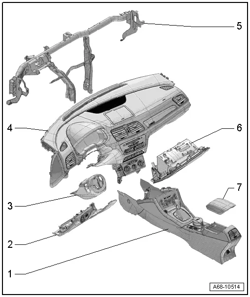
1 - Center Console
- Overview. Refer to → Chapter "Overview - Center Console".
2 - Driver Side Instrument Panel Cover
- Overview. Refer to → Chapter "Overview - Driver Side Instrument Panel Cover".
3 - Trim Panel
- For the steering column switch module
- Overview. Refer to → Chapter "Overview - Steering Column Trim Panel".
4 - Instrument Panel
 WARNING
Follow all safety precautions when working with pyrotechnic components. Refer to → Chapter "Pyrotechnic Components Safety Precautions".
- Overview. Refer to → Chapter "Overview - Instrument Panel".
5 - Central Tube
- For the instrument panel
- Overview. Refer to → Chapter "Overview - Instrument Panel Central Tube".
6 - Glove Compartment
- Overview. Refer to → Chapter "Overview - Glove Compartment".
7 - Front Center Armrest
- Overview. Refer to → Chapter "Overview - Front Center Armrest".
Overview - Driver Side Instrument Panel Cover
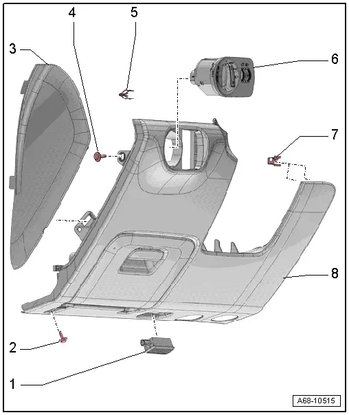
1 - Left Footwell Lamp -W9-
- Equipment levels
- Removing and installing. Refer to → Electrical Equipment; Rep. Gr.96; Lamps; Left Footwell LampW9/Right Footwell Lamp W10, Removing and Installing.
2 - Bolt
- 3 Nm
- Quantity 1 or 2 depending on the version
3 - Side Cover
- For the instrument panel
- Removing and installing. Refer to → Chapter "Instrument Panel Side Cover, Removing and Installing".
4 - Bolt
- 3 Nm
5 - Spring Clip
- For the driver side instrument panel cover
- Replace damaged or deformed spring clip
- Place in the instrument panel cover
6 - Light Switch -E1-
- Removing and Installing. Refer to → Electrical Equipment; Rep. Gr.96; Controls; Component Location Overview - Controls in the Instrument Panel.
7 - Spring Clamp
- For the driver side instrument panel cover
- Quantity: 5
- Replace damaged or deformed spring clips
- Press into the instrument panel
8 - Driver Side Instrument Panel Cover
- Removing and installing. Refer to → Chapter "Driver Side Instrument Panel Cover, Removing and Installing".
Overview - Steering Column Trim Panel
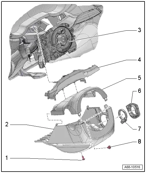
1 - Bolt
- 2.5 Nm
2 - Lower Trim Panel
- For the steering column switch module
- Removing and installing. Refer to → Chapter "Lower Steering Column Trim Panel, Removing and Installing".
3 - Steering Column Switch Module
- Removing and installing. Refer to → Electrical Equipment; Rep. Gr.94; Steering Column Switch Module; Steering Column Switch Module, Removing and Installing.
4 - Gap Cover
- For instrument cluster
- Removing and installing. Refer to → Chapter "Instrument Cluster Gap Cover, Removing and Installing".
- Press on until it engages audibly.
5 - Upper Trim Panel
- For the steering column switch module
- Removing and installing. Refer to → Chapter "Upper Steering Column Trim Panel, Removing and Installing".
6 - Mount
- For the reading coil
- Removing and installing. Refer to → Electrical Equipment; Rep. Gr.96; Immobilizer; Anti-Theft Immobilizer Reader Coil, Removing and Installing.
7 - Anti-Theft Immobilizer Reader Coil -D2-
- Equipment levels
- Removing and installing. Refer to → Electrical Equipment; Rep. Gr.96; Immobilizer; Anti-Theft Immobilizer Reader Coil, Removing and Installing.
8 - Bolt
- 2.5 Nm
- Quantity: 2
Overview - Glove Compartment
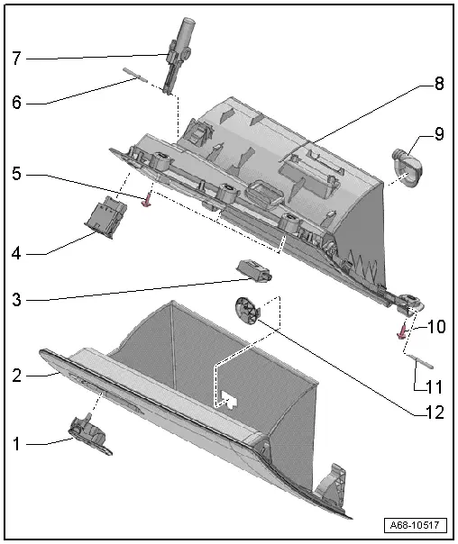
1 - Glove Compartment Opener
- Removing and installing. Refer to → Chapter "Glove Compartment Handle, Removing and Installing".
- Press into the glove compartment cover until it engages audibly
2 - Glove Compartment Lid with Storage Compartment
- Activate the glove compartment cover emergency release. Refer to → Chapter "Glove Compartment Lid Emergency Release, Operating".
- Removing and installing. Refer to → Chapter "Glove Compartment Lid, Removing and Installing".
3 - Glove Compartment Lamp -W6-
- Removing and Installing. Refer to → Electrical Equipment; Rep. Gr.96; Lamps; Glove Compartment LampW6 Removing and Installing.
4 - Front Passenger Airbag Deactivation Key Switch -E224-
NOT FOR NORTH AMERICAN MARKET
5 - Bolt
- 3 Nm
- Quantity: 3
6 - Hinge Pin
- For the brake component
7 - Lid Dampening Mechanism
- For the glove compartment lid
- With Glove Compartment Lamp Switch -E26-
- Removing and installing. Refer to → Chapter "Glove Compartment Lid Dampening Mechanism, Removing and Installing".
8 - Glove Compartment
- Removing and installing. Refer to → Chapter "Glove Compartment, Removing and Installing".
9 - Connection for Glove Compartment Cooling
- Equipment levels
10 - Bolt
- 3 Nm
- Quantity: 3
11 - Hinge Pin
- Quantity: 2
- For the glove compartment lid
12 - Vent for Glove Compartment Cooling
- Equipment levels
- Blind cover for vehicles without glove compartment cooling
READ NEXT:
 Driver Side Instrument Panel Cover, Removing and Installing
Note
As a replacement part, the new cover is delivered with an
additional attaching point.
Special tools and workshop equipment
required
Wedge Set -T10383-
Removing
- Remov
Glove Compartment Handle, Removing and Installing
Special tools and workshop equipment
required
Locking Pin (3 pc.) -T40011-
Removing
Note
If glove compartment cover does not open, it can be opened
via the emergency release. Ref
Equipment
Overview - Sun Visors
1 - Sun Visor
Allocation. Refer to the Parts Catalog.
Removing and installing. Refer to
→ Chapter "Sun Visor, Removing and Installing".
Insert visorSEE MORE:
Correct safety belt positioning
Fig. 58 Lap/shoulder belt positioning
Fig. 59 Safety belt positioning for pregnant women
Fastened safety belts only offer optimal protection
during an accident and reduce the risk of serious
injury or death when they are positioned
correctly. Furthermore, the correct safety belt
position holds the
Overview - Seat Pan, Sill Panel/Tunnel Side Seat Side Trim on Power Front
Seat
1 - Bolt
Quantity: 3
8 Nm
2 - Front Seat
3 - Seat Side Trim on the Tunnel Side
Removing and installing. Refer to
→ Chapter "Seat Side Trim on the Tunnel Side, Removing and Installing".
4 - Expanding Rivet
5 - Sill Pa