Audi Q3: Cockpit
Audi Q3 (F3) 2018-2026 Owner's Manual / Summary / Cockpit
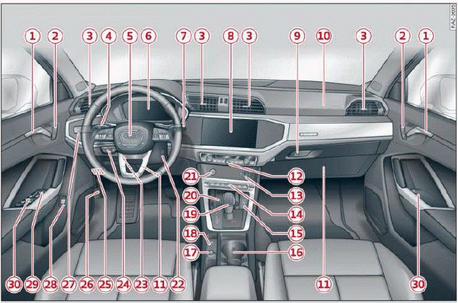
Fig. 1 Cockpit
- Door handle
- Central locking switch
- Air vent with thumbwheel
- Lever for:
- Turn signals and high beams
- High beam assistant
- Lane departure warning
- Lane guidance
- Multifunction steering wheel with:
- Horn

- Driver's airbag
- Operating buttons
- Shift paddles
- Horn
- Instrument cluster
- Windshield washer system lever
- Center display
- Lockable glove compartment
- Front passenger's airbag
- Knee airbag
- Climate control system
- MMI On/Off button
- Depending on equipment, buttons
for:
- drive select
- Electronic Stabilization Control
- Start/Stop system
- Emergency flashers
- Parking system
- Park assist
- Hill hold assist
- USB ports with charging function
- Depending on equipment:
- Cup holder
- Mount for mobile device
- Socket
- Electromechanical parking brake button
- Selector lever (automatic transmission)
- Audi phone box
- START ENGINE STOP button
- Depending on equipment:
- Starting the engine if there is a malfunction
- Ignition lock
- Steering wheel adjustment
- Lever for:
- Cruise control system
- Adaptive cruise assist
- Connection port for the On Board Diagnostic System (OBD)
- Hood release
- Buttons for:
- Lights
- All-weather lights
- Button for:
- Luggage compartment lid
- Exterior mirror adjustment
- Buttons for:
- Power windows
- Child safety lock
Tips
Some of the equipment listed here is only installed in certain models or is available as an option.
READ NEXT:
 Indicator lights overview
Description
The indicator lights in the instrument cluster
blink or turn on. They indicate functions or malfunctions.
Some warning and indicator lights
turn on when you switch the ignition on and mus
SEE MORE:
Rear Window Defogger
Rear Window Defogger -Z1-, Checking, Vehicles with Manual Climate
Control System (Heater without A/C System)
Procedure
The rear window defogger is switched on via the button
-2- on the A/C Control Module
-J301- (the Heater Control Module -J65-) control head.
Note
By pressing the
Control Module/Digital Sound System Amplifier, Removing and Installing
The Digital Sound System Control Module -J525- in the right
rear of the luggage compartment under the luggage compartment
floor covering.
Note
If replacing the control module, select the "Replace control
module" function for the corresponding control module on the
Vehicle Diagnost
© 2019-2026 Copyright www.auq3.net
