Audi Q3: Battery Tray, Removing and Installing
Battery Tray, Removing and Installing, Version 1
Removing
- Remove the air filter housing. Refer to → Rep. Gr.23; Air Filter; Air Filter Housing, Removing and Installing or → Rep. Gr.24; Air Filter; Air Filter Housing, Removing and Installing.
- Remove the battery. Refer to → Chapter "Battery in Engine Compartment, Removing and Installing, Version 1".
- Free up the wire from the battery tray.
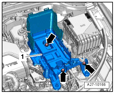
- Remove the bolts -arrows-.
- Remove the battery tray -1-.
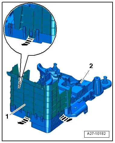
- Release the clips in direction of -arrows- and remove the rear battery jacket -1- on the battery tray -2-.
Installing
Install in reverse order of removal. Note the following:
- Install the battery. Refer to → Chapter "Battery in Engine Compartment, Removing and Installing, Version 1".
- Install the air filter housing. Refer to → Rep. Gr.23; Air Filter; Overview - Air Filter Housing or → Rep. Gr.24; Air Filter; Overview - Air Filter Housing.
Battery Tray, Removing and Installing, Version 2
Removing
- Remove the battery. Refer to → Chapter "Battery in Engine Compartment, Removing and Installing, Version 2".
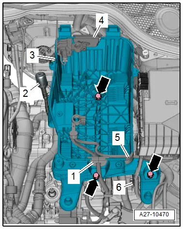
- Free up the grommets -1, 4 and 5- for the wire from the battery tray.
- Free up the wire from the battery tray.
- If equipped, free up the transmission ventilation -2- from the battery tray.
- Remove the bolts -arrows-.
- Remove the battery tray -3-.
Installing
Install in reverse order of removal. Note the following:
- Install the battery. Refer to → Chapter "Battery in Engine Compartment, Removing and Installing, Version 2".
READ NEXT:
 Battery, Charging
Preparing for Charging, Engine Compartment Battery
Procedure
WARNING
Risk of explosion on discharged battery with "Visual
indicator".
If the "Visual indicator" has no color or is light
Battery Jump Start Terminal
Overview - Battery Jump Start Terminal
1 - Bolt
6 Nm
2 - Battery Jump Start Terminal -U6-
With positive terminal grip
Removing and installing. Refer to
→ C
Start/Stop System
Component Location Overview - Start/Stop System
1 - Bracket
For the Voltage Stabilizer -J532-
2 - Connector
3 - Voltage Stabilizer -J532-
Removing and inst
SEE MORE:
Additional functions
Favorites
Applies to: vehicles with navigation system
In the favorites, you can call up frequently-used
destinations as well as your home/business address.
Accessing favorites
Applies to: MMI: Select on the home screen:
NAVIGATION > () > Favorites.
If you use myAudi navigation, your favori
Uniform tire quality grading
Tread wear
Traction AAA BC
Temperature ABC
Quality grades can be found where applicable on
the tire side wall between tread shoulder and
maximum section width fig. 154.
For example: Tread wear 200, Traction AA, Temperature
A.
All passenger car tires must conform to Federal
Safety Requirement
