Audi Q3: Start/Stop System
Component Location Overview - Start/Stop System
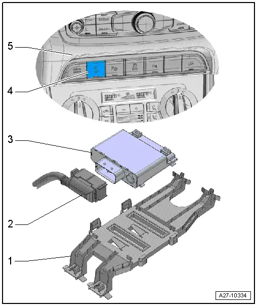
1 - Bracket
- For the Voltage Stabilizer -J532-
2 - Connector
3 - Voltage Stabilizer -J532-
- Removing and installing. Refer to → Chapter "Voltage Stabilizer, Removing and Installing".
4 - Start/Stop Mode Button -E693-
- Removing and installing. Refer to → Chapter "Lower Left Instrument Panel Button Unit, Removing and Installing".
5 - Instrument Panel
Voltage Stabilizer, Removing and Installing
Removing
- Turn off the ignition.
- Vehicles with ignition lock: Remove the key.
- Remove the left front seat. Refer to → Body Interior; Rep. Gr.72; Front Seats; Front Seat, Removing and Installing.
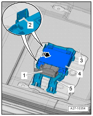
- Cut the carpet -3- in the area of the cover with scissors along the perforation and fold to the side.
- Release the tabs -2- and pivot the Voltage Stabilizer -J532--4- from the bracket -5- in direction of -arrow-.
- Disconnect the connector -1-.
Installing
Install in reverse order of removal. Note the following:
- Install the front seat. Refer to → Body Interior; Rep. Gr.72; Front Seats; Front Seat, Removing and Installing.
Special Tools
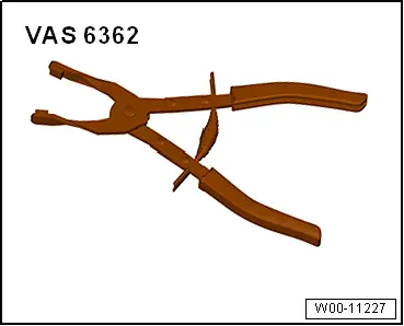
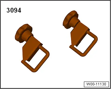
Special tools and workshop equipment required
- Hose Clip Pliers -VAS6362-
- Hose Clamps - Up To 25mm -3094-
READ NEXT:
 Instrument Cluster
Overview - Instrument Cluster
1 - Outside Air Temperature Sensor -G17-
Removing and installing. Refer to
→ Chapter "Outside Air Temperature Sensor, Removing and Installing".
Fuel Level Sensor Connector Assignment
Fuel Level Sensor -G- Connector Assignment
Disconnect the connector on the fuel tank locking flange.
For the procedure. Refer to
→ Rep. Gr.20; Fuel Delivery Unit/Fuel Level Sensor; FuSEE MORE:
Steering wheel
General information
Make sure that:
The distance between your upper body and the
steering wheel is at least 10 inches (25 cm).
Your arms are bent slightly at the elbows.
You have a sufficient view of the area around
the vehicle and you have a clear view of the instrument
cluster
You are alwa
Overview - Front Door Trim Panel
1 - Pull Handle
With switch mount
Removing and installing. Refer to
→ Chapter "Front Pull Handle, Removing and Installing".
2 - Left Front Entry Lamp -W31-
Front passenger side: Right Front Entry Lamp -W32-.
Equipment levels
Removing and installing. Re