Audi Q3: Battery, Charging
Preparing for Charging, Engine Compartment Battery
Procedure
 WARNING
Risk of explosion on discharged battery with "Visual indicator".
If the "Visual indicator" has no color or is light yellow, the battery may not be tested or charged. Jump starting must not be used! There is a risk of explosion during testing, charging or jump starting. The Battery must be replaced.
Before the battery charger can be connected, the following preparations are necessary:
 Note
Note
It is recommended that the battery is charged when installed and connected. This is the only way to ensure the charge current is incorporated into the capacity calculation for the Battery Monitoring Control Module -J367-.
- Turn off the ignition and all electrical equipment.
- Vehicles with ignition lock: Remove the key.
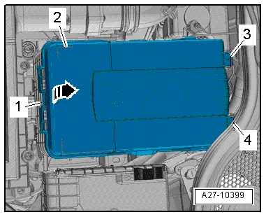
- Push the release button -1- and pivot the battery cover -2- upwards at the same time the guides on the battery trim panel mount -3 and 4- disengage at the rear.
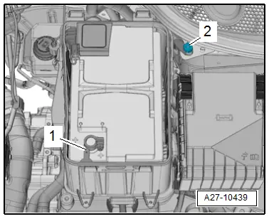
- Connect the red charging clamp "+" of the battery charger to the battery positive terminal -1- and the black charging clamp "-" to the ground service terminal -2-.
- Connect the battery charger electrical system connector and turn on the battery charger. Refer to → Electrical Equipment General Information; Rep. Gr.27; Battery, Charging.
- Leave the hood open while charging the battery.

Preparing for Charging, Battery in Luggage Compartment
Procedure
 WARNING
Risk of explosion on discharged battery with "Visual indicator".
If the "Visual indicator" has no color or is light yellow, the battery may not be tested or charged. Jump starting must not be used! There is a risk of explosion during testing, charging or jump starting. The Battery must be replaced.
Before the battery charger can be connected, the following preparations are necessary:
 Note
Note
It is recommended that the battery is charged when installed and connected. This is the only way to ensure the charge current is incorporated into the capacity calculation for the Battery Monitoring Control Module -J367-.
- Turn off the ignition and all electrical equipment.
- Vehicles with ignition lock: Remove the key.
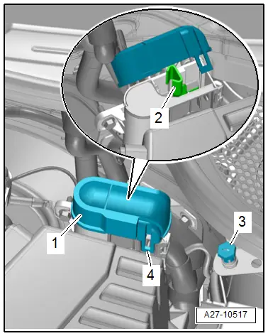
- Release the catch -4- and open the cover -1-.
- Connect the red charging clamp "+" from the battery charger to the positive service terminal -2- and the black charging clamp "-" to the ground service terminal -3-.
- Connect the battery charger electrical system connector and turn on the battery charger. Refer to → Electrical Equipment General Information; Rep. Gr.27; Battery, Charging.
- Leave the hood open while charging the battery.

Preliminary Work for Battery Support Mode, Engine Compartment Battery
Procedure
- Push the release button -1- and pivot the battery cover -2- upwards at the same time the guides on the battery trim panel mount -3 and 4- disengage at the rear.
- Connect the red charging clamp "+" of the battery charger to the battery positive terminal -1- and the black charging clamp "-" to the ground service terminal -2-.

- Connect the battery charger electrical system connector and turn on the battery charger. Refer to → Electrical Equipment General Information; Rep. Gr.27; Battery, Charging.
Preliminary Work for Battery Support Mode, Battery in Luggage Compartment
Procedure
- Release the catch -4- and open the cover -1-.
- Connect the red charging clamp "+" from the battery charger to the positive service terminal -2- and the black charging clamp "-" to the ground service terminal -3-.
- Connect the battery charger electrical system connector and turn on the battery charger. Refer to → Electrical Equipment General Information; Rep. Gr.27; Battery, Charging.
READ NEXT:
 Battery Jump Start Terminal
Overview - Battery Jump Start Terminal
1 - Bolt
6 Nm
2 - Battery Jump Start Terminal -U6-
With positive terminal grip
Removing and installing. Refer to
→ C
Start/Stop System
Component Location Overview - Start/Stop System
1 - Bracket
For the Voltage Stabilizer -J532-
2 - Connector
3 - Voltage Stabilizer -J532-
Removing and inst
SEE MORE:
Operating in the cockpit
Fig. 78 Deluxe automatic climate control with 2 zones/3 zones: controls
Observe the safety precautions.
The functions can be switched on and off by
pressing the buttons or adjusted by turning the
knob. When the function is switched on, the LED
in the respective button or knob turns on.
Cooling mod
Side Wall Lettering
Example: Dunlop SP Sport 9000
1 - Size Designation (215/55 ZR16)
Label on PAX tires. Refer to
→ Chapter "Run-Flat Tire (PAX), Labeling On Sidewall"
2 - Manufacturer (Trade Name)
3 - Tread Designation
4 - Label for Tubeless Tires
5 -&
