Audi Q3: Wheel Bearing Unit, Removing and Installing
Special tools and workshop equipment required
- Torque Wrench 1332 40-200Nm -VAG1332-
Removing
- Loosen the drive axle threaded connection on the wheel side. Refer to → Chapter "Drive Axle Threaded Connection, Loosening and Tightening".
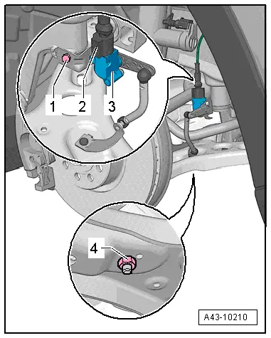
- If installed, remove the nut -4- and free up the coupling rod from the Left Front Level Control System Sensor -G78--3-.
- Remove the ABS speed sensor. Refer to → Brake System; Rep. Gr.45; Sensors; Right/Left Front ABS Wheel Speed Sensor G45/G47, Removing and Installing.
- Remove the brake rotor. Refer to → Brake System; Rep. Gr.46; Front Brakes; Brake Rotor, Removing and Installing.
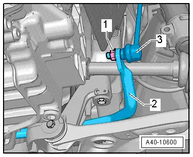
- Remove the nut -1-, remove the coupling rod -3- from the stabilizer bar -2- and pivot aside.
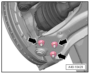
- Remove the nuts -arrows-.
- Remove the control arm from the ball joint.
- Remove the drive axle outer joint from the wheel hub.
- Secure drive axle to body using wire.
- Reconnect the ball joint in the control arm.
- Install the nuts -arrows-.
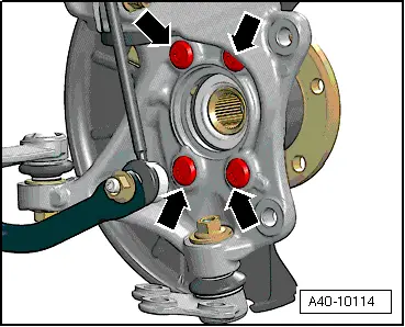
- Remove the bolts -arrows-.
- Remove wheel bearing unit from wheel bearing housing.
 Caution
Avoid contaminating with dirt and damaging the seal when lifting, setting down/storing.
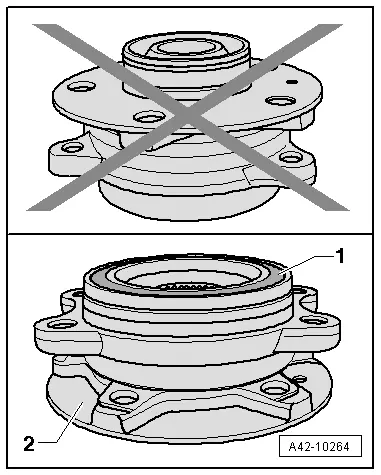
- The wheel bearing -1- must face up in order to remove the wheel bearing unit.
- Always set the wheel bearing unit down on the wheel hub -2-.
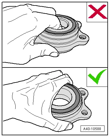
- Never reach into the inside when lifting the wheel bearing.
- Hold the wheel bearing only on the outside.
Installing
Install in reverse order of removal while noting the following:
- Install the brake caliper. Refer to → Brake System; Rep. Gr.46; Front Brakes; Brake Caliper, Removing and Installing.
Tightening Specifications
- Brake rotor.
READ NEXT:
 Overview - Drive Axle
Overview - Drive Axle, Drive Axle with CV Joint VL107
1 - Bolt
200 Nm +180º
Always replace if removed
Loosening and tightening the twelve-point bolt
→ Chapter "Drive Axl
Drive Axle, Removing and Installing, Drive Axle with Bolted CV Joint VL
107
Removing
- Loosen the drive axle threaded connection on the wheel side.
Refer to
→ Chapter "Drive Axle Threaded Connection, Loosening and
Tightening".
- Remove the front wheel
Drive Axle, Removing and Installing, Drive Axle with Triple Roller Joint
AAR3300i, Mounted on Transmission Stub Shaft
Special tools and workshop equipment
required
Slide Hammer Set -VW771-
Tensioning Strap -T10038-
Puller - Driveshaft -T10382-
Torque Wrench 1332 40-200Nm -VAG1332-
Digital Torque Wrench
SEE MORE:
Brake Caliper Piston, Removing and Installing
Brake Caliper Piston, Removing and Installing, Single-Piston Brake
Special tools and workshop equipment
required
Trim Removal Wedge -3409-
Piston Resetting Tool -T10145-
Piston Resetting Tool - Cap /6 -T10146/6- from Piston
Resetting Tool - Caps /1,/2,/3,/4,/5 -T10146-
Removing
T
Refrigerant Circuit, Charging with Service Station
Note
The entire refrigerant charge can be added to either the
high or low pressure side. Refer to
→ Chapter "Refrigerant R134a Capacities, Refrigerant Oil and
Approved Refrigerant Oils".
The work procedure is always to be performed as described in
the operating instructi
