Audi Q3: Drive Axle, Removing and Installing, Drive Axle with Triple Roller Joint AAR3300i, Mounted on Transmission Stub Shaft
Special tools and workshop equipment required
- Slide Hammer Set -VW771-
- Tensioning Strap -T10038-
- Puller - Driveshaft -T10382-
- Torque Wrench 1332 40-200Nm -VAG1332-
- Digital Torque Wrench -VAG1756A-
Removing
- Loosen the drive axle threaded connection on the wheel side. Refer to → Chapter "Drive Axle Threaded Connection, Loosening and Tightening".
- Remove the front wheel. Refer to → Chapter "Wheels and Tires".
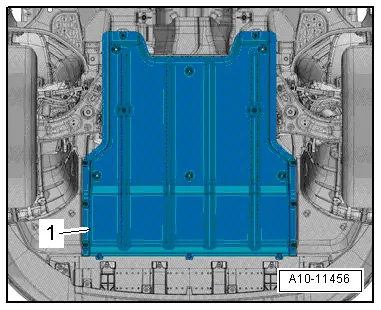
- Remove the noise insulation -1-. Refer to → Body Exterior; Rep. Gr.66; Noise Insulation; Noise Insulation, Removing and Installing.
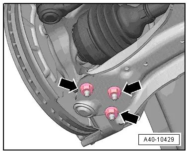
- Remove the nuts -arrows-.
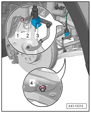
- If installed, disconnect the vehicle level control system sensor coupling rod from the control arm by removing the nut -4-.
- Remove both the wheel bearing housing and ball joint from the control arm.
![]() Note
Note
Pay attention during the assembly work that the ball joint rubber boot is not damaged. If necessary protect the ball joint rubber boot against damage.
- Slide outer joint out of wheel hub by hand.
- Secure the drive axle to keep it from falling down.
![]() Note
Note
Do not let the drive axle hang down. The inner joint could be damaged if it is bent too far.
- Remove the right drive axle heat shield. Refer to → Chapter "Drive Axle Heat Shield, Removing and Installing".
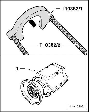
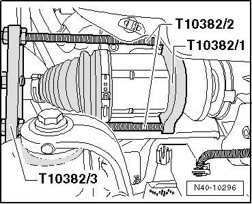
- Align the Puller - Driveshaft -T10382-.
For the CV joint -1-, the surface -arrow- of the Puller - Driveshaft - Removing Plate -T10382/1- must face the Puller - Driveshaft - Spindles -T10382/2-.
- Attach the Puller - Driveshaft -T10382- to the Slide Hammer Set -VW771-.
![]() Note
Note
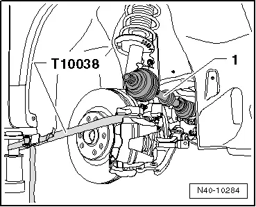
In order to remove the drive axle from the transmission using the Puller - Driveshaft -T10382-, the suspension strut and all its components must be pulled to the back.
- Pull the suspension strut and its components using the Tensioning Strap -T10038- as far as possible to the back, for example on the workshop hoist arm, until the Puller - Driveshaft -T10382- can be installed parallel to the drive axle.
- Install the Puller - Driveshaft -T10382- and remove the drive axle.
- Remove the drive axle from the vehicle.
Installing
Installation is reverse of removal, noting the following:
- Remove any paint residue and/or corrosion in threads/splines of outer joint.
Only for the right side of the vehicle and all wheel drive
![]() Caution
Caution
- This ensures that the stub shaft circlip engages in the differential bevel gear correctly.
- This also prevents leaks.
- Tap on the front side of the stub shaft using a plastic mallet.
Continued for Both Sides
- Install the new circlip into the stub shaft groove on the transmission.
- Apply approximately 2 grams of grease all around the splines on the transmission. Refer to the Parts Catalog.
- Bring outer and inner splines of the transmission and the CV joint into engagement.
- Grab the drive axle by hand and push it into the joint up to the stop.
- Now push the ball joint with one jerk onto the transmission stub shaft.
- Slide the joint piece with the drive axle onto the transmission pins until the circlip engages.
![]() Note
Note
Never use a hammer or mallet!
- Make sure the joint is seated correctly, to do this pull the joint against the resistance of the securing ring.
![]() Caution
Caution
When checking, only pull on the joint piece and not on the drive axle.
- Lightly coat the splines on the outer joint with assembly paste before installing the outer joint into the wheel hub. Refer to the Parts Catalog.
- Tighten the twelve-point bolt on the driveshaft. Refer to → Chapter "Drive Axle Threaded Connection, Loosening and Tightening".
- Install the front wheel. Refer to → Chapter "Wheels and Tires".
- On vehicles with electronically controlled damping, perform the function "Adapt the control position" with the Vehicle Diagnosis Tester.
- If the control position was reprogrammed and if the vehicle has lane assist, then it will then be necessary to calibrate the driver assistance systems front camera. Refer to → Chapter "Driver Assistance Systems Front Camera, Calibrating".
- On vehicles with level control system sensor, perform headlamp basic setting. Refer to → Electrical Equipment; Rep. Gr.94; Headlamp, Adjusting.
READ NEXT:
 Drive Axle, Removing and Installing, Left Drive Axle with CV Joint, Inserted
with Inner Splines
Drive Axle, Removing and Installing, Left Drive Axle with CV Joint, Inserted
with Inner Splines
Special tools and workshop equipment
required
Puller - Driveshaft -T10382-
Torque Wrench 1332 40-200Nm -VAG1332-
Slide Hammer Set -VW771-
Removing
- Loosen the drive axle threaded c
Drive Axle, Removing and Installing, Right Drive Axle with CV Joint,
Inserted with Inner Splines
Special tools and workshop equipment
required
Slide Hammer Set -VW771-
Tensioning Strap -T10038-
Puller - Driveshaft -T10382-
Torque Wrench 1332 40-200Nm -VAG1332-
Digital Torque Wrench
Drive Axle Threaded Connection, Loosening and Tightening
Special tools and workshop equipment
required
Socket AF 24 mm -T10361A-
Digital Torque Wrench -VAG1756A-
The wheel bearing must not be under a load while the drive
axle threaded connectio
SEE MORE:
Battery, Disconnecting and Connecting
Battery in Engine Compartment, Disconnecting and Connecting
Caution
Accident risk.
When working on pyrotechnic components (such as
airbags and belt tensioners), the battery must be
disconnected with the ignition switched on.
Disconnecting
- Turn off the ignition.
- Vehi
Ball Joint, Removing and Installing
Special tools and workshop equipment
required
Puller - Ball Joint -3287A-
Digital Torque Wrench -VAG1756A-
Torque Wrench 1332 Insert - Ring Wrench - 18mm -VAG1332/10-
Removing
- Loosen drive axle bolt on the wheel hub. Refer to
→ Chapter "Drive Axle Threaded Connection, Lo
