Audi Q3: Wheel Bearing Housing Bonded Rubber Bushing, Replacing
Wheel Bearing Housing Bonded Rubber Bushing, Replacing, FWD Vehicles
Special tools and workshop equipment required
- Bearing Installer - Control Arm -3346-
- Bearing Installer - Carrier Bearing -3350-
- Fitting Sleeve -3378-
- Torque Adapter -3390-
- Torque Wrench 1332 40-200Nm -VAG1332-
Removing
- Measure dimension from center of wheel to lower edge of wheel housing. Refer to → Chapter "Wheel Bearing in Curb Weight, Lifting Vehicles with Coil Spring".
- Remove the coil spring. Refer to → Chapter "Spring, Removing and Installing".
- Remove the wheel bearing/wheel bearing unit. Refer to → Chapter "Wheel Bearing Unit, FWD, Removing and Installing".
- Remove the brake shield. Refer to → Brake System; Rep. Gr.46; Rear Brakes; Brake Shield, Removing and Installing.
- Remove the bolts -lower arrows- on vehicles with level control system sensor.
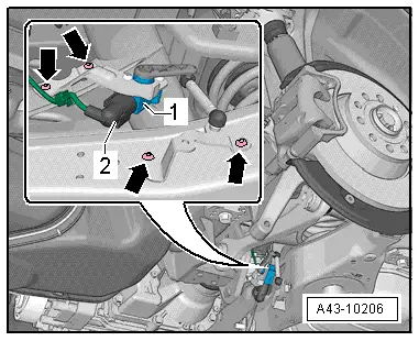
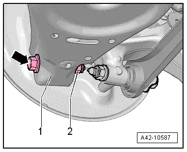
- Remove the nut -2- and remove the bolt -arrow- for the lower control arm -1-.

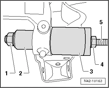
Pressing out bonded rubber bushing
1 - Bearing Installer - Control Arm - Nut -3346/3-
2 - Torque Adapter -3390-
3 - Bearing Installer - Carrier Bearing -3350-
4 - Nut, commercially available
5 - Bearing Installer - Control Arm - Spindle -3346/2-
- Remove bonded rubber bushing by turning spindle.
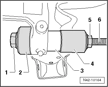
Installing the bonded rubber bushing
1 - Bearing Installer - Control Arm - Nut -3346/3-
2 - Bearing Installer - Control Arm -3346-
3 - Bonded rubber bushing
4 - Fitting Sleeve -3378-
5 - Nut, commercially available
6 - Bearing Installer - Control Arm - Spindle -3346/2-
- Install bonded rubber bushing by turning support arm bearing installation tool.
 Note
Note
- Do not use lubricant!
- Insert bearing with care so it is not canted.

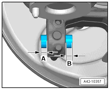
- Check the installed position after installing the bonded rubber bushing.
- Dimensions -A- and -B- must be the same (each measured, if applicable, at a spot where there is no seam/burr).
- Install the bonded rubber bushing again if dimensions -A- and -B- are different.
Use a commercially available 27 mm socket wrench in place of the Fitting Sleeve -3378- to install the bonded rubber bushing.
Installing
Installation is reverse of removal, noting the following:
Bolting at wheel bearing housing may only occur when the dimension between wheel hub center and lower edge of wheel housing, measured before assembly, is achieved. Refer to → Chapter "Wheel Bearing in Curb Weight, Lifting Vehicles with Coil Spring".
- Install the brake caliper. Refer to → Brake System; Rep. Gr.46; Rear Brakes; Brake Caliper, Removing and Installing.
- Install the coil spring. Refer to → Chapter "Spring, Removing and Installing".
- An axle alignment may be required. Refer to → Chapter "Evaluating Need for Axle Alignment".
- On vehicles with electronically controlled damping, perform the function "Adapt the control position" with the Vehicle Diagnostic Tester.
- If the control position was reprogrammed and if the vehicle has lane assist, then it will then be necessary to calibrate the driver assistance systems front camera. Refer to → Chapter "Driver Assistance Systems Front Camera, Calibrating".
- On vehicles with level control system sensor, perform headlamp basic setting. Refer to → Electrical Equipment; Rep. Gr.94; Headlamp, Adjusting.
Wheel Bearing Housing Bonded Rubber Bushing, Replacing, AWD Vehicles
Special tools and workshop equipment required
- Bearing Installer - Control Arm -3346-
- Bearing Installer - Carrier Bearing -3350-
- Fitting Sleeve -3378-
- Torque Adapter -3390-
- Torque Wrench 1332 40-200Nm -VAG1332-
Removing
- Measure dimension from center of wheel to lower edge of wheel housing. Refer to → Chapter "Wheel Bearing in Curb Weight, Lifting Vehicles with Coil Spring".
- Remove the coil spring. Refer to → Chapter "Spring, Removing and Installing".
- Remove the brake caliper with the brake carrier and secure it to the body using wire. Refer to → Brake System; Rep. Gr.46; Rear Brakes; Brake Caliper, Removing and Installing.
 Note
Note
Do not let the brake caliper hang on the brake hose - risk of damage.
- Remove the brake shield. Refer to → Brake System; Rep. Gr.46; Rear Brakes; Brake Shield, Removing and Installing.
- Remove the lower bolts -arrows- on vehicles with a Level Control System Sensor.

- Remove the nut -2- and remove the bolt -arrow- for the lower control arm -1-.
Pressing out bonded rubber bushing
- Install tools as shown in illustration.
1 - Bearing Installer - Control Arm - Nut -3346/3-
2 - Torque Adapter -3390-
3 - Bearing Installer - Carrier Bearing -3350-
4 - Nut, commercially available
5 - Bearing Installer - Control Arm - Spindle -3346/2-
- Remove bonded rubber bushing by turning spindle.

Installing the bonded rubber bushing
- Install tools as shown in illustration.
1 - Bearing Installer - Control Arm - Nut -3346/3-
2 - Bearing Installer - Control Arm -3346-
3 - Bonded rubber bushing
4 - Fitting Sleeve -3378-
5 - Nut, commercially available
6 - Bearing Installer - Control Arm - Spindle -3346/2-
- Install bonded rubber bushing by turning support arm bearing installation tool.
 Note
Note
- Do not use lubricant!
- Insert bearing with care so it is not canted.
- Check the installed position after installing the bonded rubber bushing.
- Dimensions -A- and -B- must be the same (each measured, if applicable, at a spot where there is no seam/burr).
- Install the bonded rubber bushing again if dimensions -A- and -B- are different.
Use a commercially available 27 mm socket wrench in place of the Fitting Sleeve -3378- to install the bonded rubber bushing.

Installing
Installation is reverse of removal, noting the following:
Bolting at wheel bearing housing may only occur when the dimension between wheel hub center and lower edge of wheel housing, measured before assembly, is achieved. Refer to → Chapter "Wheel Bearing in Curb Weight, Lifting Vehicles with Coil Spring".
- Install the brake caliper. Refer to → Brake System; Rep. Gr.46; Rear Brakes; Brake Caliper, Removing and Installing.
- Install the coil spring. Refer to → Chapter "Spring, Removing and Installing".
- An axle alignment may be required. Refer to → Chapter "Evaluating Need for Axle Alignment".
- Perform the headlamp basic setting. Refer to Vehicle Diagnosis Tester.
- For vehicles with electronic damping, perform the basic setting using the Vehicle Diagnosis Tester.
READ NEXT:
 Trailing Arm with Mounting Bracket, Removing and Installing
Trailing Arm with Mounting Bracket, Removing and Installing, FWD Vehicles
Special tools and workshop equipment
required
Torque Wrench 1332 40-200Nm -VAG1332-
Engine/Gearbox Jack Adapter - Whe
Trailing Arm, Servicing
Trailing Arm, Servicing, FWD Vehicles
Special tools and workshop equipment
required
Press Plate -VW401-
Press Plate -VW402-
Front Subframe Mount Kit -3372-
Hydraulic Press - Bushing Assem
Overview - Drive Axle
Overview - Drive Axle, Drive Axle with 100 mm Inner CV Joint
Note
Grease joint again when replacing protective joint boot.
1 - Outer CV Joint
Replace only as complete unitSEE MORE:
Correct safety belt positioning
Fig. 58 Lap/shoulder belt positioning
Fig. 59 Safety belt positioning for pregnant women
Fastened safety belts only offer optimal protection
during an accident and reduce the risk of serious
injury or death when they are positioned
correctly. Furthermore, the correct safety belt
position holds the
Front Center Armrest
Overview - Front Center Armrest
1 - Front Center Armrest
Removing and installing. Refer to
→ Chapter "Front Center Armrest, Removing and Installing".
2 - Lower Cover
For the center armrest cushion
Engage in the front of the center armrest cushion and pres