Audi Q3: Overview - Drive Axle
Overview - Drive Axle, Drive Axle with 100 mm Inner CV Joint
 Note
Note
Grease joint again when replacing protective joint boot.
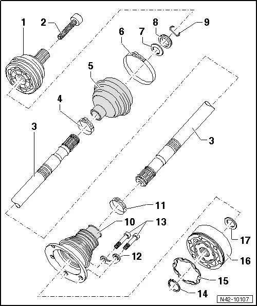
1 - Outer CV Joint
- Replace only as complete unit.
- When installing the joint on the profile shaft, the splines on the profile shaft must be lightly coated with grease used in joint.
- Checking. Refer to → Chapter "Outer CV Joint, Checking".
- Removing. Refer to → Fig. "Removing the outer CV joint".
- Grease table.
- Installing.
2 - Bolt
- Twelve-point bolt tightening specification: 200 Nm + 180º additional turn
- Always replace if removed
- Before installing, clean the threads in the CV joint with a tap.
The vehicle must be on the ground when tightening.
- Loosening and tightening the twelve-point bolt. Refer to
3 - Profile Shaft
4 - Clamp
- Replace
- Tensioning. Refer to or → Fig. "Clamps for rubber protective joint boots, tensioning"
5 - CV Boot for Outer CV Joint
- Without vent hole
- Check for tears and scuffing
6 - Clamp
- Replace
- Tensioning. Refer to or → Fig. "Clamps for rubber protective joint boots, tensioning"
7 - Plate Spring
- Installed position.
8 - Spacer Ring (Plastic)
- Installed position.
9 - Locking Ring
- Replace
- Insert in shaft groove
10 - CV Boot for Inner CV Joint
- Without vent hole
- Check for tears and scuffing
- Drive off CV joint using drift
- Coat the sealing surface with D 454 300 A2 before installing it on the CV joint
11 - Clamp
- Replace
- Tensioning. Refer to or → Fig. "Clamps for rubber protective joint boots, tensioning"
12 - Locking Plate
13 - Internal multipoint Bolt
- First tighten diagonally to 10 Nm, then tighten diagonally again to the tightening specification.
- M8 tightening specification: diagonal sequence to 40 Nm
- M10 tightening specification: diagonal sequence to 70 Nm
- Always replace if removed
14 - Locking Ring
- Replace
- Remove and install using Circlip Pliers -VW161A-. Refer to → Fig. "Circlip, removing and installing".
15 - Seal
- Bonding surface on CV joint must be free of grease and oil!
16 - Inner CV Joint
- Replace only as complete unit.
- Grease table, page.
- Checking. Refer to → Chapter "Inner CV Joint, Checking".
- Removing.
- When installing the joint on the profile shaft, the splines on the profile shaft must be lightly coated with grease used in joint.
- Installing.
17 - Plate Spring
- Installed position.
Overview - Drive Axle, Drive Axle with 82 mm Outer CV Joint
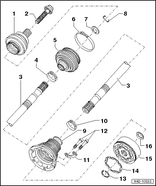
1 - Outer CV Joint
- Replace only as complete unit.
- Removing. Refer to → Fig. "Outer CV joint, pressing off".
- Installing: using a plastic mallet, drive onto the shaft as far as the stop
- Divide the grease evenly in the joint
- Checking. Refer to → Chapter "Outer CV Joint, Checking".
2 - Bolt
- Twelve-point bolt tightening specification: 200 Nm + 180º additional turn. Refer to → Chapter "Drive Axle Threaded Connection, Loosening and Tightening".
- Always replace if removed
- Before installing, clean the threads in the CV joint with a tap.
3 - Drive Axle
- For allocation. Refer to the Parts Catalog.
4 - Clamp
- Always replace if removed
- Tensioning.
5 - CV Boot
- Check for tears and scuffing
- Material: polyelastomer
6 - Clamp
- Always replace if removed
- Tensioning.
7 - Plate Spring
- With inner spline
- Installed position.
8 - Locking Ring
- Always replace if removed
- Insert in shaft groove
9 - CV Boot for CV joint
- Material: polyelastomer
- Without vent hole
- Check for tears and scuffing
- Drive off CV joint using drift
- Coat the sealing surface with -D 454 300 A2- before installing it on the CV joint
10 - Clamp
- Always replace if removed
- Tensioning.
11 - Locking Plate
12 - Internal multipoint Bolt
- M8 tightening specification: diagonal sequence to 40 Nm.
- M10 tightening specification: diagonal sequence to 70 Nm.
- Always replace if removed
- First tighten diagonally to 10 Nm, then tighten diagonally again to the tightening specification
13 - Locking Ring
- Always replace if removed
- Remove and install using Circlip Pliers -VW161A-.
14 - Seal
- Always replace if removed
- Bonding surface on CV joint must be free of grease and oil!
15 - Inner CV Joint
- Replace only as complete unit.
- Divide the grease evenly in the joint
- Removing. Refer to
- Installing. Refer to
- Checking. Refer to → Chapter "Inner CV Joint, Checking".
16 - Plate Spring
- With inner spline
- Installed position.
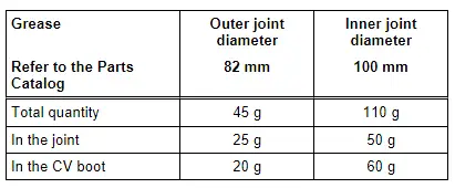
Filling Joints with Grease
READ NEXT:
 Drive Axle, Removing and Installing
Removing
- Measure dimension from center of wheel to lower edge of
wheel housing. Refer to
→ Chapter "Wheel Bearing in Curb Weight, Lifting Vehicles with
Coil Spring".
- Loose
Drive Axle, Disassembling and Assembling
Drive Axle, Disassembling and Assembling, Drive Axle with 100 mm Inner CV
Joint
Special tools and workshop equipment
required
Tripod Joint Tool -T10065-
Torque Wrench 1331 5-50Nm -VAG1331-
Drive Axle Threaded Connection, Loosening and Tightening
Special tools and workshop equipment
required
Socket AF 24 mm -T10361A-
Digital Torque Wrench -VAG1756A-
The wheel bearing must not be under a load while the
driveshaft threaded connectio
SEE MORE:
Fuel
Types of gasoline
The correct gasoline grade is stated on the inside
of the fuel filler door.
The vehicle is equipped with a catalytic converter
and must only be driven with unleaded gasoline.
Audi recommends using TOP TIER Detergent Gasoline.
For additional information on TOP TIER Detergent
Gasol
Suspension Strut and Upper Control Arm
Overview - Suspension Strut and Upper Control Arm
1 - Shock Absorber
On vehicles with electronically controlled damping, perform the
function "Adapt the control position" with the Vehicle Diagnostic
Tester.
If the control position was reprogrammed and if the vehicle has lane
