Audi Q3: Vehicle Electrical System, General Repair Information
Electrical Equipment General Information / Electrical System / Audi Q3 (8U) 2011-2018 Service Manual / Vehicle Electrical System, General Repair Information
 Caution
When disconnecting and connecting battery, the procedure must be followed as described in the Repair Manual.
 WARNING
Some tools are supplied with a tool safety clip, which is slid over the tool points after using the tool, in order to protect other workers from injuries and tool points from damage.
- Observe the current notes in the corresponding repair manual for all repairs.
- Observe country-specific regulations.
- Before working on the electrical system, the battery Ground (GND) cable must be disconnected. By disconnecting the battery GND cable (current disruption), the electrical system is guaranteed to be safe to work on. Disconnecting the positive battery cable is only required when removing the battery.
- Before starting a repair, the cause of the damage must be eliminated first (for example sharp edges on chassis parts, faulty electrical consumers, corrosion etc.).
- For the wiring harnesses if possible a high quality replacement part is always delivered. This means that previously not required connector housings may be present on the replacement part.
- Additionally bend back the non-necessary connector housing when possible in a dry area of the vehicle and route them so that no noises can result.
- Additionally to prevent capillary action seal the non-necessary connector housing and single wires in wet areas of the vehicle with water tight heat-shrinkable tube. The necessary components to seal the single wires can be found in the Parts Catalog.
- Further information, for example, installing and removing the individual components, can be found in the appropriate Repair Manual.
- Soldering is not permissible for repairs to the vehicle electrical system.
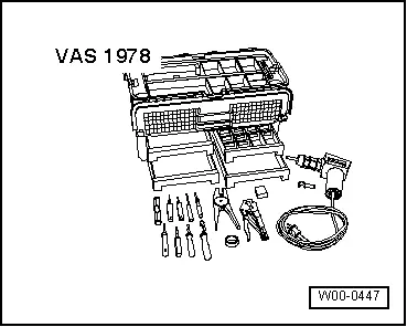
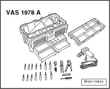
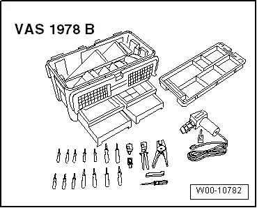
- Wiring harness and connector repairs on the vehicle electrical system may only be performed using Wiring Harness Repair Set -VAS1978B- and previous versions such as the Wiring Harness Repair Set -VAS631001- and the Wiring Harness Repair Set -VAS631003-. Only use the yellow wires from the corresponding wiring harness-repair kit.
- Wiring harness repairs may not be performed again in the wrapping of the vehicle-specific wiring harness and are to be marked with yellow adhesive tape. This indicated a previous repair.

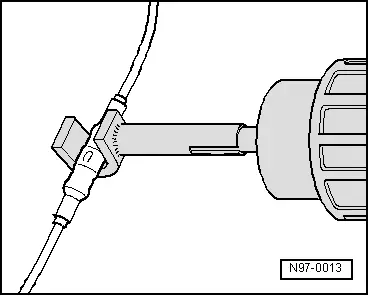
- Pinch and butt connectors must not be repaired. If necessary, lay a wire parallel to the faulty wire. After crimping, crimp connections must be heat-shrunk using hot air gun to prevent moisture penetration. Connectors with corresponding heat-shrinkable tube must be protected moisture penetration.
- Always observe the supplementary notes for repairing wiring harnesses on airbag- and seat belt tensioner systems, fiber optic cables, CAN bus lines, FlexRay wires, and antenna wires.
- A function test must be performed after every repair. If necessary, check Diagnostic Trouble Code (DTC) memory, erase and/or bring systems into basic setting.
- If possible, do not loosen grounding straps from the body (danger of corrosion).

- Not all wire cross-sections in the vehicle are contained in the Wiring Harness Repair Set -VAS1978B- and its previous versions. If the required wire cross-section is not present, the next greater cross-section must be used.

- Heat-resistant wires have been installed in the vehicle at various locations, mainly in the engine compartment. Heat-resistant wires can be recognized by their somewhat duller and softer insulation. Only heat-resistant wires may be used to repair these wires.
READ NEXT:
 Wiring Harness Repair Set
Wiring Harness Repair Set -VAS1978-
The Wiring Harness Repair Set -VAS1978- makes optimal repair
quality possible in the realm of vehicle electronics. Using the
tools, repairs affecting harness c
Tool Descriptions
Crimping Pliers with Insert
The Crimping Pliers without Insert -VAS1978/1- with Crimping
Pliers - Insert 2 -VAS1978/2- is a component of the Wiring
Harness Repair Set -VAS1978- and is used to cri
Airbag and Belt Tensioner Wires, Repairing
In addition to the general repairs on wiring harnesses, the following methods
and instructions must be observed for repairs on airbag- and seat belt tensioner
wires:
WARNING
The airSEE MORE:
Passenger Occupant Detection System
Component Location Overview - Passenger Occupant Detection System
WARNING
The replacement part (service kit) for the passenger
occupant detection system is already precalibrated and must not
be separated under any circumstances. The service kit consists
of:
Passenger Occupant D
Steering Column Electronics Control Module Connector Assignment
Steering Column Electronics Control Module -J527- Connector Assignment,
with Mechanical Ignition Lock
The Steering Column Electronics Control Module -J527- is
part of the complete system "steering column switch module". It
receives the signal for example from the steering column switch.
© 2019-2026 Copyright www.auq3.net | 0.0143
