Audi Q3: Steering Column Electronics Control Module Connector Assignment
Steering Column Electronics Control Module -J527- Connector Assignment, with Mechanical Ignition Lock
- The Steering Column Electronics Control Module -J527- is part of the complete system "steering column switch module". It receives the signal for example from the steering column switch.
- Check the Steering Column Electronics Control Module -J527- in "Guided Fault Finding". Refer to Vehicle Diagnostic Tester.
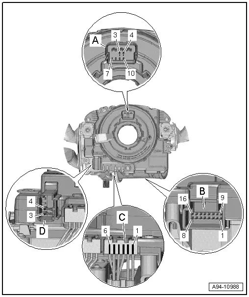
A - Steering Wheel Connector Mount
1 - Not assigned
2 - Not assigned
3 - Driver Airbag Igniter -N95-"+"
4 - Driver Airbag Igniter -N95-"-"
5 - Not assigned
6 - Not assigned
7 - Ground
8 - Cruise control system "On, Off"/horn-signal
9 - LIN bus
10 - Terminal 15 multifunction steering wheel
11 - Not used
12 - Not used
B - Vehicle Electrical System Connector Mount
1 - Voltage supply terminal 30
2 - Voltage supply terminal 31
3 - Comfort CAN bus Low
4 - Comfort CAN bus High
5 - Cruise control system "On, Off"
6 - Terminal 50
7 - Terminal S
8 - Not assigned
9 - Not used
10 - Not used
11 - P locking mechanism
12 - Powertrain CAN bus Low
13 - Powertrain CAN bus High
14 - Terminal 15
15 - Not used
16 - Not used
C - Ignition Lock Connector Mount
1 - Ignition/Starter Switch Ground
2 - Ignition/Starter Switch Charge
3 - Terminal 15
4 - S
5 - Terminal 50
6 - Terminal 30
D - Vehicle Electrical System Airbag-Connection Connector Mount
3 - Driver Airbag Igniter -N95-"+"
4 - Driver Airbag Igniter -N95-"-"
5 - Not assigned
6 - Not assigned
Steering Column Electronics Control Module -J527- Connector Assignment, with Electronic Ignition Lock
- The Steering Column Electronics Control Module -J527- is part of the complete system "steering column switch module". It receives the signal for example from the steering column switch.
- Check the Steering Column Electronics Control Module -J527- in "Guided Fault Finding". Refer to Vehicle Diagnostic Tester.

A - Steering Wheel Connector Mount
1 - Not assigned
2 - Not assigned
3 - Driver Airbag Igniter -N95-"+"
4 - Driver Airbag Igniter -N95-"-"
5 - Not assigned
6 - Not assigned
7 - Ground
8 - Cruise control system "On, Off"/horn-signal
9 - LIN bus
10 - Terminal 15 multifunction steering wheel
11 - Not used
12 - Not used
B - Vehicle Electrical System Connector Mount
1 - Voltage supply terminal 30
2 - Voltage supply terminal 31
3 - Comfort CAN bus Low
4 - Comfort CAN bus High
5 - Cruise control system "On, Off"
6 - Not assigned
7- Not used
8 - Not used
9 - Not used
10 - Not used
11 - Not used
12 - Powertrain CAN bus Low
13 - Powertrain CAN bus High
14 - Not used
15 - Not used
16 - Electronic steering column lock "Locking possible"
C - Not Assigned
D - Vehicle Electrical System Airbag-Connection Connector Mount
3 - Driver Airbag Igniter -N95-"+"
4 - Driver Airbag Igniter -N95-"-"
5 - Not assigned
6 - Not assigned
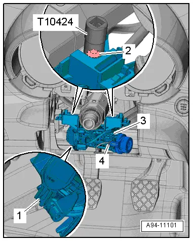
Steering Lock Housing, Removing and Installing
Special tools and workshop equipment required
- 7/16 Inch Extractor -T10424US-
Removing
- Remove the steering column switch module. Refer to → Chapter "Steering Column Switch Module, Removing and Installing, with Mechanical Ignition Lock".
- Disconnect the connectors -1 and 4-.
- Remove the shear bolt -2- using the 7/16 Inch Extractor -T10424US-.
- Remove the steering lock housing -3-.
 Note
Note
If the shear bolt cannot be removed using the 7/16 Inch Extractor -T10424US-, use an angled hand drill and 8.5 mm diameter bit to drill it out.
To replace the steering lock housing, the ignition/starter switch and lock cylinder must be removed.
- To remove the ignition/starter switch. Refer to → Chapter "Ignition/Starter Switch, Removing and Installing".
- To remove the lock cylinder. Refer to → Chapter "Lock Cylinder, Removing and Installing".
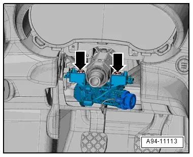
Installing
Install in reverse order of removal. Note the following:
- Tighten the new bolts -arrows- until the head shears off.
- Install the steering column switch module. Refer to → Chapter "Steering Column Switch Module, Removing and Installing, with Mechanical Ignition Lock".
READ NEXT:
 Overview - Parking Aid
In the Front of the Vehicle
1 - Right Front Parking Aid Sensor -G252-
In the front bumper cover
Removing and installing. Refer to
→ Chapter "Front Parking Aid Sensor, Remov
Parking Aid Control Module -J446-, Removing and Installing
Note
On vehicles with parallel parking assist the Parallel
Parking Assistance Control Module -J791- is integrated in the
Parking Aid Control Module -J446-.
- If replacing the contr
Front Parking Aid Sensor, Removing and Installing
Front Parking Aid Sensors, Removing and Installing, through MY 2014
Right/Left Front Parking Aid Sensor -G252-/-G255-
Special tools and workshop equipment
required
Hook Tool -T40207-
RemoviSEE MORE:
Additional functions
Favorites
Applies to: vehicles with navigation system
In the favorites, you can call up frequently-used
destinations as well as your home/business address.
Accessing favorites
Applies to: MMI: Select on the home screen:
NAVIGATION > () > Favorites.
If you use myAudi navigation, your favori
Radio Installation Instructions
Retrofitting Radio Systems
General Information
Before installing radios and telephone systems (radio
systems), disconnect the negative terminal of the Battery -A-.
Refer to
→Electrical Equipment; Rep. Gr.27.
Use the applicable wiring diagrams. Refer to
→ Wiring diagrams, Trou