Audi Q3: Trailing Arm, Servicing
Trailing Arm, Servicing, FWD Vehicles
Special tools and workshop equipment required
- Press Plate -VW401-
- Press Plate -VW402-
- Front Subframe Mount Kit -3372-
- Hydraulic Press - Bushing Assembly Tool Kit -T10230-
Pressing out the bonded rubber bushing
- Remove trailing arm with mounting bracket. Refer to → Chapter "Trailing Arm with Mounting Bracket, Removing and Installing, FWD Vehicles".
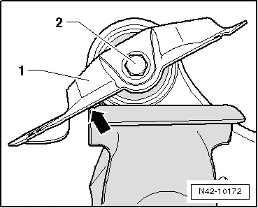
- Clamp the trailing arm in the vise so that the mounting bracket -1- contacts the vise -arrow-.
- Remove the bolt -2-.
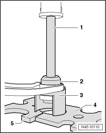
- Install tools as shown in the illustration.
1 - Hydraulic Press - Bushing Assembly Tool Kit-Pipe -T10230/3-
2 - Hydraulic Press - Bushing Assembly Tool Kit-Press Piece -T10230/10-
3 - Front Subframe Mount Kit -3372-
4 - Press Plate -VW401-
5 - Press Plate -VW402-
- Press out the bonded rubber mount.

Installing the bonded rubber bushing
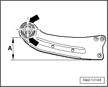
- Place the trailing arm on a flat surface.
- Position the trailing arm so that the dimension -A- 113 mm is reached.
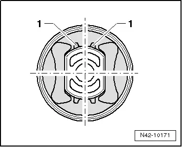
- In this position, apply a vertical line (marking on the upper and lower edge of the bushing) that is centered with the trailing arm bushing -arrows-.

- Position the bonded rubber bushing on the trailing arm so that the marked line is between the raised sections -1-.
 Note
Note
Always make sure that the bonded rubber bushing is in the correct installation position to the trailing arm bushing.
- Install tools as shown in the illustration.
1 - Hydraulic Press - Bushing Assembly Tool Kit - Tube -T10230/5-
2 - Hydraulic Press - Bushing Assembly Tool Kit-Thrust Plate -T10230/12-, the chamfer must face the bonded rubber bushing
3 - Bonded rubber bushing
4 - Front Subframe Mount Kit -3372-
5 - Press Plate -VW402-
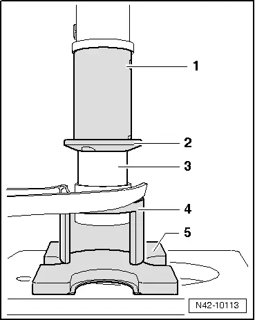
- Press in bonded rubber bushing flush.
- Install the mounting bracket on trailing arm.
- Install trailing arm with mounting bracket. Refer to → Chapter "Trailing Arm with Mounting Bracket, Removing and Installing, FWD Vehicles".
Trailing Arm, Servicing, AWD Vehicles
Special tools and workshop equipment required
- Press Plate -VW401-
- Press Plate -VW402-
- Front Subframe Mount Kit -3372-
- Hydraulic Press - Bushing Assembly Tool Kit -T10230-
Pressing out the bonded rubber bushing
- Remove trailing arm with mounting bracket. Refer to → Chapter "Trailing Arm with Mounting Bracket, Removing and Installing, FWD Vehicles".
- Clamp the trailing arm into vise so that the mounting bracket -1- makes contact at vise -arrow-.

- Remove the bolt -2-.
- Install tools as shown in the illustration.
1 - Hydraulic Press - Bushing Assembly Tool Kit-Pipe -T10230/3-
2 - Hydraulic Press - Bushing Assembly Tool Kit-Press Piece -T10230/10-
3 - Front Subframe Mount Kit -3372-
4 - Press Plate -VW401-
5 - Press Plate -VW402-
- Press out the bonded rubber mount.

Installing the bonded rubber bushing
- Place the trailing arm on a flat surface.
- Position the trailing arm so that the dimension -A- 113 mm is reached.
- In this position, apply a vertical line (marking on the upper and lower edge of the bushing) that is centered with the trailing arm bushing -arrows-.
- Position the bonded rubber bushing on the trailing arm so that the marked line is between the raised sections -1-.
 Note
Note
Always make sure that the bonded rubber bushing is in the correct installation position to the trailing arm bushing.

- Install tools as shown in the illustration.
1 - Hydraulic Press - Bushing Assembly Tool Kit - Tube -T10230/5-
2 - Hydraulic Press - Bushing Assembly Tool Kit-Thrust Plate -T10230/12-, the chamfer must face the bonded rubber bushing
3 - Bonded rubber bushing
4 - Front Subframe Mount Kit -3372-
5 - Press Plate -VW402-

- Press bonded rubber bushing in flush.
- Install the mounting bracket on trailing arm.
- Install trailing arm with mounting bracket. Refer to → Chapter "Trailing Arm with Mounting Bracket, Removing and Installing, FWD Vehicles".
READ NEXT:
 Overview - Drive Axle
Overview - Drive Axle, Drive Axle with 100 mm Inner CV Joint
Note
Grease joint again when replacing protective joint boot.
1 - Outer CV Joint
Replace only as complete unit
Drive Axle, Removing and Installing
Removing
- Measure dimension from center of wheel to lower edge of
wheel housing. Refer to
→ Chapter "Wheel Bearing in Curb Weight, Lifting Vehicles with
Coil Spring".
- Loose
Drive Axle, Disassembling and Assembling
Drive Axle, Disassembling and Assembling, Drive Axle with 100 mm Inner CV
Joint
Special tools and workshop equipment
required
Tripod Joint Tool -T10065-
Torque Wrench 1331 5-50Nm -VAG1331-
SEE MORE:
Introduction
Applies to: vehicles with telephone
You can operate various telephone functions easily
through the MMI in your vehicle.
Depending on the country and the vehicle equipment,
the following options may be available:
Connecting a cell phone with Bluetooth
Using two telephones
Using the Audi phone bo
Door Lock, Removing and Installing
Door Lock, Removing and Installing
Caution
There is a risk of malfunctions.
The door lock must be removed and installed together
with the bracket to prevent over-bending the cable when
disengaging and engaging it.
The cable must be disconnected from/attached to the
lever on the d