Audi Q3: Drive Axle, Removing and Installing
Removing
- Measure dimension from center of wheel to lower edge of wheel housing. Refer to → Chapter "Wheel Bearing in Curb Weight, Lifting Vehicles with Coil Spring".
- Loosen the drive axle threaded connection. Refer to → Chapter "Drive Axle Threaded Connection, Loosening and Tightening".
- Remove the coil spring. Refer to → Chapter "Spring, Removing and Installing".
- Remove the bolts -lower arrows- on vehicles with a Level Control System Sensor.
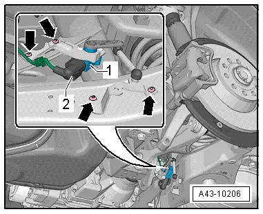
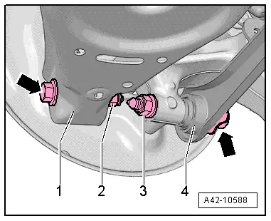
- Remove the bolts -arrows- for the lower control arm -1- and tie rod -4- from the wheel bearing housing.
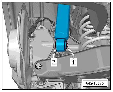
- Remove the bolt -1- and remove it with the washer -2-.
- Loosen the drive axle on the transmission side.
- Pivot the wheel bearing housing outward and remove the drive axle from wheel bearing splines.
- Remove the drive axle.
Installing
Install in reverse order of removal while noting the following:
- Bolting at wheel bearing housing may only occur when the dimension between wheel hub center and lower edge of wheel housing, measured before assembly, is achieved. Refer to → Chapter "Wheel Bearing in Curb Weight, Lifting Vehicles with Coil Spring".
- Lightly coat the splines on the outer joint with assembly paste before installing the outer joint into the wheel hub. Refer to the Parts Catalog.
- Install the coil spring. Refer to → Chapter "Spring, Removing and Installing".
- On vehicles with electronically controlled damping, perform the function "Adapt the control position" with the Vehicle Diagnosis Tester.
- If the control position was reprogrammed and if the vehicle has lane assist, then it will then be necessary to calibrate the driver assistance systems front camera. Refer to → Chapter "Driver Assistance Systems Front Camera, Calibrating".
- On vehicles with level control system sensor, perform headlamp basic setting. Refer to → Electrical Equipment; Rep. Gr.94; Headlamp, Adjusting.
Tightening Specifications
- Drive axle threaded connection to the rear final drive.
READ NEXT:
 Drive Axle, Disassembling and Assembling
Drive Axle, Disassembling and Assembling, Drive Axle with 100 mm Inner CV
Joint
Special tools and workshop equipment
required
Tripod Joint Tool -T10065-
Torque Wrench 1331 5-50Nm -VAG1331-
Drive Axle Threaded Connection, Loosening and Tightening
Special tools and workshop equipment
required
Socket AF 24 mm -T10361A-
Digital Torque Wrench -VAG1756A-
The wheel bearing must not be under a load while the
driveshaft threaded connectio
Special Tools
Special tools and workshop equipment
required
Shock Absorber Set -T10001-
Tensioning Strap -T10038-
Tripod Joint Tool -T10065-
Locating Pins -T10096-
Engine/Gearbox JacSEE MORE:
Adjusting the display
Fig. 6 Center display: adjusting the display
Switching the view
Applies to: Audi virtual cockpit
Press the VIEW button to switch between the
default view 1 and the enhanced view 2.
Adjusting the layout
Applies to: Audi virtual cockpit
Depending on the vehicle equipment, various layouts
may be a
Rear Three-Point Seat Belt, Removing and Installing
Outer Rear Three-Point Seat Belt, Removing and Installing
Removing
- Remove the rear outer belt end fitting. Refer to
→ Chapter "Rear Outer Belt End Fitting, Removing and Installing".
- Remove the luggage compartment side trim. Refer to
→ Chapter "Luggage Compartment Sid