Audi Q3: Trailer Hitch
Overview - Trailer Hitch Socket and Towing Recognition Control Module
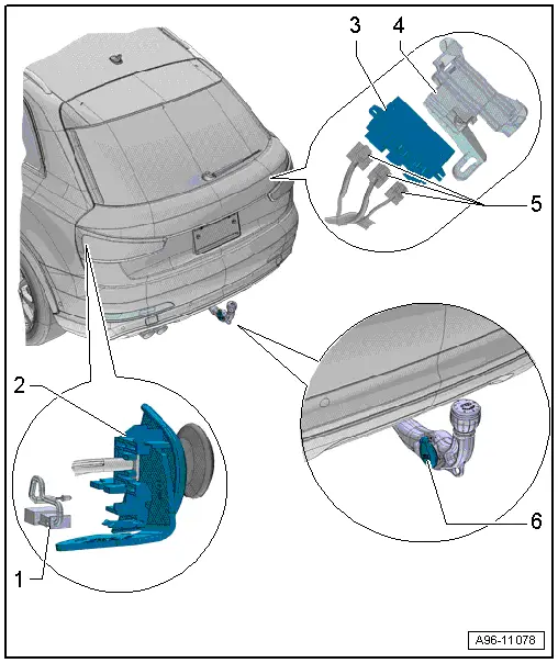
1 - LED Indicator Lamp
- Trailer Hitch -Locked- Indicator Lamp -K226-, Trailer Hitch -Unlocked- Indicator Lamp -K227-
- Make sure the trailer hitch is locked correctly
- Removing and installing. Refer to → Chapter "LED Indicator Lamp, Removing and Installing".
2 - Mount
- For the cable
- For unlocking the trailer hitch
3 - Towing Recognition Control Module -J345-
- Removing and installing. Refer to → Chapter "Towing Recognition Control Module -J345-, Removing and Installing".
4 - Frame
- For Towing Recognition Control Module -J345-
5 - Connectors
6 - Trailer Socket -U10-
- Removing and Installing. Refer to → Electrical Equipment General Information; Rep. Gr.96; Trailer Hitch.
- For the connector assignment. Refer to → Electrical Equipment General Information; Rep. Gr.96; Trailer Hitch.
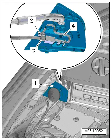
LED Indicator Lamp, Removing and Installing
Removing
- Remove the luggage compartment left side trim panel cover.
- Disconnect the connector -2-.
- Remove the LED indicator lamp -3- from the cable mount -1- and free up the electric wire -4-.
Installing
Install in reverse order of removal.
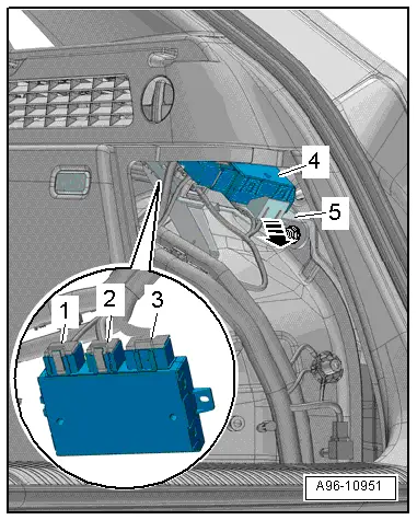
Towing Recognition Control Module -J345-, Removing and Installing
- If replacing the control module, select the "Replace Control Module" function see Vehicle Diagnostic Tester.
Removing
- Remove the luggage compartment right side trim panel cover.
- Open the clip -arrow-.
- Remove the control module -4- from the frame.
- Disconnect the connectors -1, 2 and 3-.
Installing
Install in reverse order of removal.
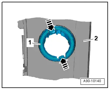
- Remove the illumination ring -1- with the Socket Illumination Bulb -L42- from the center console rear cover -2-.
Installing
Install in reverse order of removal. Note the following:
- The illumination ring can only be inserted into the mount in one position.
- Install the 12 V socket. Refer to → Chapter "12 V Socket 2 -U18-, Removing and Installing".
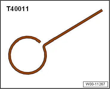
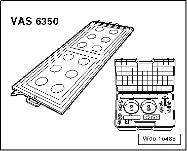
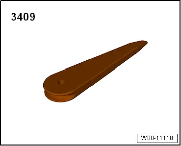
Special Tools
Locking Pin -T40011-
Calibration Tool -VAS6350-
Trim Removal Wedge -3409-
READ NEXT:
 Component Location Overview - Relay Carriers, Fuse Panels and E-Boxes
Overview - E-box, Wire Junction, Fuse Panel, Suppressor
1 - Nut
9 Nm
2 - Wiring Harness
3 - Nut
4.5 Nm
4 - Suppressor -C24-
Removing and i
E-Box, Removing and Installing
Removing
- Remove the relay and fuse panel and move them to the side
with the wires still connected. Refer to
→ Chapter "Relay and Fuse Panel B -SB- in the E-Box, Removing
and Insta
SEE MORE:
Left/Right Headlamp Beam Adjustment Motor -V48-/-V49-, Removing and
Installing
Left/Right Headlamp Beam Adjustment Motor -V48-/-V49-, Removing and
Installing, Halogen Headlamps
Removing
- Remove the headlamp housing. Refer to
→ Chapter "Headlamp, Removing and Installing, Halogen Headlamps".
- If equipped, remove the bolts -1 and
3-.
- Open the t
Check Valve, Checking
Check valve is removed, refer to
→ Chapter "Check Valve, Removing and Installing".
Note
The check valve is installed directly in front of the vacuum
pump.
Valve must allow air to flow in direction of arrow.
Valve must remain closed in opposite direction.
