Audi Q3: E-Box, Removing and Installing
Removing
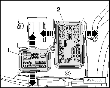
- Remove the relay and fuse panel and move them to the side with the wires still connected. Refer to → Chapter "Relay and Fuse Panel B -SB- in the E-Box, Removing and Installing".
- Release the retaining tabs in direction of -arrows-.
- If equipped, push the 26-pin connector -1- to the side and out of the left engine compartment E-box.
- Move the 40-pin connector -2- to the side and out of the left engine compartment E-box
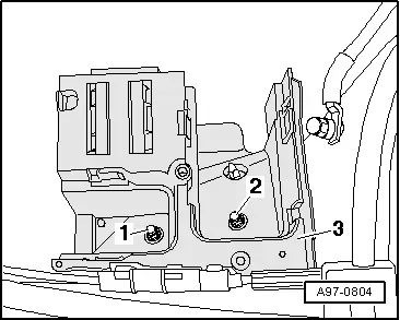
- Remove the nuts -1 and 2-.
- Remove the left engine compartment E-box -3- upward.
- If equipped, remove the relay panel -2- under the E-box in the left of the engine compartment -1- in direction of -arrow-.
 Note
Note
Check the exact assignment in the current wiring diagram. Refer to → Wiring diagrams, Troubleshooting & Component locations.
Installing
Install in reverse order of removal. Note the following:
- Install the relay and fuse panel B. Refer to → Chapter "Relay and Fuse Panel B -SB- in the E-Box, Removing and Installing".
E-Box Connector Station, Removing and Installing
Relay and Fuse Panel B -SB- in the E-Box, Removing and Installing
Removing
- With the ignition switched off, disconnect the ground cable from the battery. Refer to → Chapter "Battery, Disconnecting and Connecting".
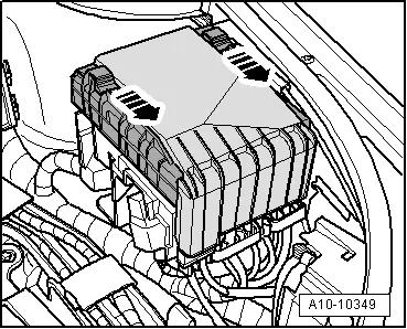
- Push both latches in the direction of -arrow- and remove the left engine compartment E-box cover.
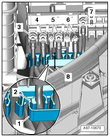
- When re-installing, identify the wires on the threaded connectors.
- Cut through the cable tie -8-.
- Release the retaining clips -2- and move the wiring harness -1- to the side.
- Remove the nuts -3 through 7- and disconnect the wires from the retainers.
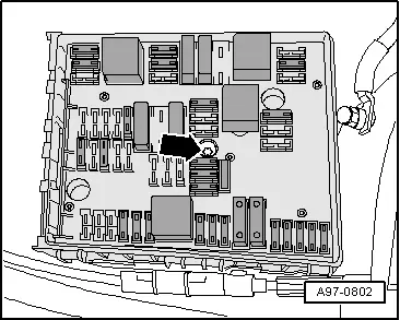
- Remove the bolts -arrow-.
- Remove the relay and fuse panel B from the left engine compartment E-box.
Installing
Install in reverse order of removal. Note the following:
- Mount the relay and fuse panel B on the engine compartment E-box. Tighten the central bolt; when doing so the connectors will be pushed up.
- Connect and tighten the wires according to the markings on the left engine compartment E-box main fuse panel.
- Connect the battery. Required actions. Refer to → Chapter "Battery, Disconnecting and Connecting".
Plenum Chamber Connector Station Cover, Removing and Installing
Removing
- Remove the windshield wiper motor. Refer to → Chapter "Windshield Wiper Motor -V-, Removing and Installing".
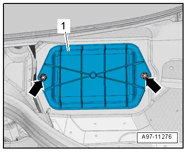
- Remove the nuts -arrows-.
- Remove the cover -1- from the plenum chamber connector station.
Installing
Install in reverse order of removal, observing the following:
- Install the windshield wiper motor. Refer to → Chapter "Windshield Wiper Motor -V-, Removing and Installing".
- Adjust the windshield wiper arms. Refer to → Chapter "Windshield Wiper Arms, Adjusting".
Suppressor -C24-, Removing and Installing
Removing
- With the ignition switched off, disconnect the ground cable from the battery. Refer to → Chapter "Battery in Luggage Compartment, Disconnecting and Connecting".
- Remove the air filter housing. Refer to → Rep. Gr.23; Air Filter; Air Filter Housing, Removing and Installing or → Rep. Gr.24; Air Filter; Air Filter Housing, Removing and Installing.
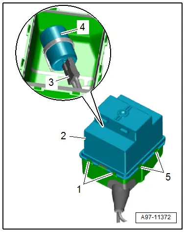
- Remove the relay and fuse panel and move them to the side with the wires still connected. Refer to → Chapter "Relay and Fuse Panel B -SB- in the E-Box, Removing and Installing".
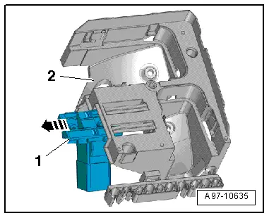
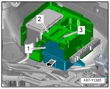
- Release the catch -3- and remove the mounting box -1- under the E-box -2- in direction of -arrow-.
- Release the catches -1 and 5- and remove the mounting box-upper section -2-.
- Disconnect the connector -3-.
- Free up the suppressor -4- and remove.
Installing
Install in reverse order of removal. Note the following:
- Install the air filter housing. Refer to → Rep. Gr.23; Air Filter; Air Filter Housing, Removing and Installing or → Rep. Gr.24; Air Filter; Air Filter Housing, Removing and Installing.
- Connect the battery. Required actions.
Fuse Panel C -SC-, Removing and Installing
Removing
- Remove the driver side instrument panel cover. Refer to → Body Interior; Rep. Gr.68; Storage Compartments/Covers; Driver Side Instrument Panel Cover, Removing and Installing.
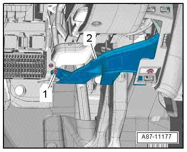
- Remove the bolt -1-.
- Remove the footwell vent -2-.
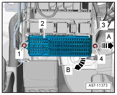
- Remove the bolts -1 and 4-.
- Push the mount -3- slightly to the side in direction of -arrow A- and pivot out the fuse panel C -2- downward in direction -arrow B-.
- Release the 16-Pin Connector -T16- and remove from the mount.
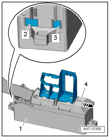
- Push the cover -4- on the fuse panel C in the direction of -arrow-.
 Note
Note
Check the exact assignment in the current wiring diagram. Refer to → Wiring diagrams, Troubleshooting & Component locations.
- Remove the fuses -2 and 3- for the connector terminal.
- Pull the fuses and remove the connectors from the fuse panel C -1-.
Installing
Install in reverse order of removal. Note the following:
- Install the driver side instrument panel cover. Refer to → Body Interior; Rep. Gr.68; Storage Compartments/Covers; Driver Side Instrument Panel Cover, Removing and Installing.
READ NEXT:
 Relay and Fuse Carriers Behind Instrument Panel on Driver Side, Removing and
Installing
Relay and Fuse Carriers Behind Instrument Panel on Driver Side, Removing and
Installing
Relay Carrier on Vehicle Electrical System Control Module, Removing and
Installing
Removing
- Remove the driver side instrument panel cover. Refer to
→ Body Interior; Rep. Gr.68;
Control Modules
Component Location Overview - Control Modules
Component Location Overview - Control Modules
1 - Vehicle Electrical System Control Module -J519-
Removing and installing. Refer to
â†
Connectors
Connector Component Location Overview
1 - Right Front Door Cut-Off Connector
Disconnecting. Refer to
→ Chapter "Left Door Cut-Off Connector, Disconnecting".
2 - SEE MORE:
Power windows
Opening and closing the windows
Fig. 35 Driver's door: power window switch
Power window switches:
Left front door
Right front door
Left rear door
Right rear door
Opening and closing the windows
The driver can control all power windows. All
power window switches are equipped with a twostage
fu
Rearview camera and peripheral cameras
Introduction
Applies to: vehicles with rearview camera/peripheral cameras
Fig. 113 Orientation line display when parking
Depending on the vehicle equipment, a rearview
camera or multiple peripheral cameras may be
available.
The rearview camera helps you to park or maneuver
using the orientation li