Audi Q3: Subframe, Servicing
Tools and Preliminary Work
Special tools and workshop equipment required
- Hydraulic Press -VAS6178-
- with Bearing Installer - Wheel Hub/Bearing Kit - Pressure Head -T10205/13- from the Bearing Installer - Wheel Hub/Bearing Kit -T10205A-
- Pneumatic/Hydraulic Foot Pump -VAS6179-
- Engine and Gearbox Jack -VAS6931-
- Tensioning Strap -T10038-
- through MY 2012 Locating Pins -T10096-
- from MY 2013 Assembly Tool, Sub-frame Alignment -T10486A-
- Subframe Bushing Assembly Tool Kit -T10356-
Subframe bonded rubber bushing, replacing, only for AWD vehicles
Procedure
- Remove the coil springs. Refer to → Chapter "Spring, Removing and Installing".
- Remove the stabilizer bar. Refer to → Chapter "Stabilizer Bar, Removing and Installing".
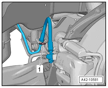
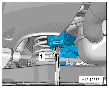
- Remove the clip -1-.
- Free up the brake line.
 Note
Note
Do not disconnect the brake line.
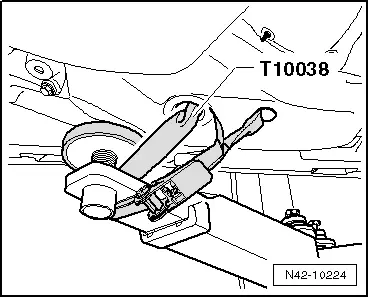
- Now secure vehicle on both sides to lifting arms on hoist with Tensioning Strap -T10038-.
 WARNING
The vehicle could slide off the hoist if it is not secured.
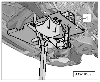
- Move the Engine and Gearbox Jack -VAS6931--1- under the subframe and secure it using the tensioning strap.
 Caution
There is a risk of damaging the subframe threaded connection threads on the body.
- The subframe bolts on the body must not be loosened or tightened with an impact wrench.
- Always install all bolts by hand for the first few turns.
- Remove the front hex bolt -1- from both sides.
 Note
Note
Only the left side of the vehicle is shown in the illustration.
To secure the subframe, the Locating Pins -T10096- (through MY 2012) must be installed at positions -1- on both sides of the vehicle one after the other. Use Assembly Tool, Sub-frame Alignment -T10486A- from MY 2013.
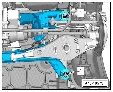
- Secure the subframe position using the locating pins -1-.
 Note
Note
The locating pins may only be tightened to a maximum of 20 Nm, since otherwise the locating pin threads will be damaged.
- Replace subframe bolts one after the other on both sides using the locating pins and tighten the locating pins to 20 Nm.
The subframe position is now secured.
- Lower the subframe 10 cm using Engine and Gearbox Jack -VAS6931-.
- Mark the installation position of bonded rubber bushing to subframe, for example, with a felt-tip pen.

Front Bonded Rubber Bushing, Servicing
Front bonded rubber bushing, removing
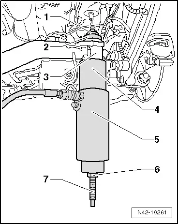
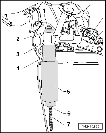
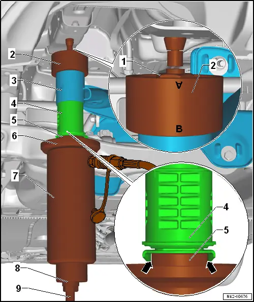
- Install special tools as depicted in the illustration.
1 - Hydraulic Press - Rear Subframe Bushing Tool Kit-Nut -T10263/5-
2 - Subframe Bushing Assembly Tool Kit-Press Piece -T10356/1-
3 - Subframe
4 - Subframe Bushing Assembly Tool Kit-Tube -T10356/2-
5 - Hydraulic Press -VAS6178- with Bearing Installer - Wheel Hub/Bearing Kit- Adapter 13 -T10205/13-
6 - Hydraulic Press - Rear Subframe Bushing Tool Kit-Nut -T10263/5-
7 - Hydraulic Press - Rear Subframe Bushing Tool Kit-Spindle -T10263/4-
- Pretension special tools.
- Pull out bonded rubber bushing by operating pump.
 Note
Note
The bearing outer race is sheared off when the bonded rubber bushing is removed. There is a loud crack when this happens.
- After removing the rubber bonded bushing, it must be removed from the Subframe Bushing Assembly Tool Kit - Tube -T10356/2-.
Installing the front bonded rubber bushing
Install in reverse order of removal. Note the following:
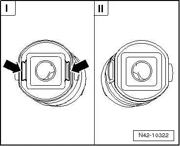
Distinguishing characteristic, rubber bonded bushing
I - Front bonded rubber bushing
II - Rear Bonded Rubber Bushing
The front bonded rubber bushings have two openings -arrows- on the top and have slightly different installation heights. Refer to the Parts Catalog.
Bonded rubber bushing must be installed in the correct direction, note marking on subframe.

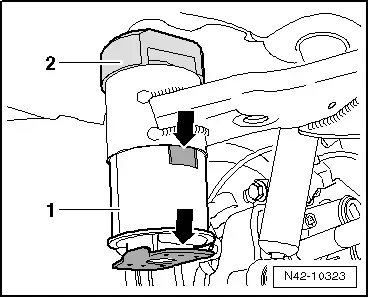
- Install the rubber bonded bushing -1- into the subframe, so that the tab and the plate -arrows- face perpendicular to direction of travel.
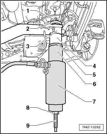
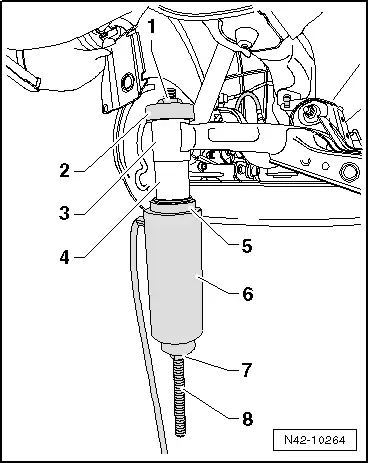
- Insert special tools with bonded rubber bushing into subframe as illustrated.
through MY 2013: Refer to Parts Catalog
1 - Hydraulic Press - Rear Subframe Bushing Tool Kit-Nut -T10263/5-
2 - Subframe Bushing Assembly Tool Kit - Guide Piece -T10356/3- with side A toward subframe
3 - Subframe
4 - Bonded Rubber Bushing
5 - Subframe Bushing Assembly Tool Kit - Press Piece -T10356/4- with side A toward bonded rubber bushing
6 - Subframe Bushing Assembly Tool Kit-Tube -T10356/2-
7 - Hydraulic Press -VAS6178- with Bearing Installer - Wheel Hub/Bearing Kit- Adapter 13 -T10205/13-
8 - Hydraulic Press - Rear Subframe Bushing Tool Kit-Nut -T10263/5-
9 - Hydraulic Press - Rear Subframe Bushing Tool Kit-Spindle -T10263/4-
From MY 2013: Refer to → Electronic Parts Catalog (ETKA)
1 - Hydraulic Press - Rear Subframe Bushing Tool Kit-Nut -T10263/5-
2 - Assembly Tool - Bushing -T10356/7- with side A toward subframe
3 - Subframe
4 - Bonded Rubber Bushing
5 - Assembly Tool - Bushing -T10356/8- with side A toward bonded rubber bushing
6 - Subframe Bushing Assembly Tool Kit-Tube -T10356/2-
7 - Hydraulic Press -VAS6178- with Bearing Installer - Wheel Hub/Bearing Kit- Adapter 13 -T10205/13-
8 - Hydraulic Press - Rear Subframe Bushing Tool Kit-Nut -T10263/5-
9 - Hydraulic Press - Rear Subframe Bushing Tool Kit-Spindle -T10263/4-
- Pretension special tool with bonded rubber bushing.
- Carefully insert bonded rubber bushing by operating pump until collar lies on subframe "without a gap".
Rear Bonded Rubber Bushing, Servicing
Pulling out rear bonded rubber bushing
- Move the Engine and Gearbox Jack -VAS6931--1- under the subframe and secure it using the tensioning strap.

 Caution
There is a risk of damaging the subframe threaded connection threads on the body.
- The subframe bolts on the body must not be loosened or tightened with an impact wrench.
- Always install all bolts by hand for the first few turns.
- Remove the rear hex bolt -1- from both sides.
 Note
Note
Only the left side of the vehicle is shown in the illustration.
To secure the subframe, the Locating Pins -T10096- (through MY 2012) must be installed at positions -1- on both sides of the vehicle one after the other. Use Assembly Tool, Subframe Alignment -T10486A- from MY 2013.

- Secure the subframe position using the locating pins.
 Note
Note
The locating pins may only be tightened to a maximum of 20 Nm, since otherwise the locating pin threads will be damaged.
- Replace subframe bolts one after the other on both sides using the locating pins and tighten the locating pins to 20 Nm.
The subframe position is now secured.
- Lower the subframe 10 cm using Engine and Gearbox Jack -VAS6931-.
- Mark the installation position of bonded rubber bushing to subframe, for example, with a felt-tip pen.
- Install special tools as depicted in the illustration.
1 - Hydraulic Press - Rear Subframe Bushing Tool Kit-Nut -T10263/5-
2 - Subframe Bushing Assembly Tool Kit - Thrust Piece-T10356/5-
3 - Subframe
4 - Subframe Bushing Assembly Tool Kit - Tube -T10356/6-
5 - Hydraulic Press -VAS6178- with Bearing Installer - Wheel Hub/Bearing Kit- Adapter 13 -T10205/13-
6 - Hydraulic Press - Rear Subframe Bushing Tool Kit-Nut -T10263/5-
7 - Hydraulic Press - Rear Subframe Bushing Tool Kit-Spindle -T10263/4-
- Pretension special tools.
- Pull out bonded rubber bushing by operating pump.
 Note
Note
The bearing outer race is sheared off when the bonded rubber bushing is removed. There is a loud crack when this happens.
- After removing the rubber bonded bushing, it must be removed from the Subframe Bushing Assembly Tool Kit - Tube -T10356/2-.
Pulling in rear bonded rubber bushing
Install in reverse order of removal. Note the following:
Distinguishing characteristic, rubber bonded bushing
I - Front bonded rubber bushing
II - Rear Bonded Rubber Bushing
The front bonded rubber bushings have two openings -arrows- on the top and have slightly different installation heights. Refer to the Parts Catalog.
Bonded rubber bushing must be installed in the correct direction, note marking on subframe.
through MY 2013: Refer to Parts Catalog
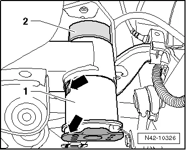
- Install the rubber bonded bushing -1- into the subframe, so that the tab and the plate -arrows- face perpendicular to direction of travel.
- Mount the Hydraulic Press - Rear Subframe Bushing Tool Kit - Pressure Piece -T10263/3--2- so that the flat side faces perpendicular to direction of travel.
- Insert special tools with bonded rubber bushing into subframe as illustrated.
1 - Hydraulic Press - Rear Subframe Bushing Tool Kit-Nut -T10263/5-
2 - Subframe Bushing Assembly Tool Kit - Guide Piece -T10356/3- with side B toward subframe
3 - Subframe
4 - Bonded Rubber Bushing
5 - Subframe Bushing Assembly Tool Kit - Press Piece -T10356/4- with side B toward bonded rubber bushing
6 - Hydraulic Press -VAS6178- with Bearing Installer - Wheel Hub/Bearing Kit- Adapter 13 -T10205/13-
7 - Hydraulic Press - Rear Subframe Bushing Tool Kit-Nut -T10263/5-
8 - Hydraulic Press - Rear Subframe Bushing Tool Kit-Spindle -T10263/4-
From MY 2013: Refer to Parts Catalog
- Insert special tools with bonded rubber bushing into subframe as illustrated.
1 - Hydraulic Press - Rear Subframe Bushing Tool Kit - Nut -T10263/5-
2 - Assembly Tool - Bushing -T10356/7- - the marking -B- points to the subframe
3 - Subframe
4 - adjust the bonded rubber bushing to the marks (the marks need to align)
5 - Assembly Tool - Bushing -T10356/8- - the flattened sides need to fit into the cover of the bonded rubber bushing -arrows-.
6 - Bearing Installer - Wheel Hub/Bearing Kit - Gripping Device -T10205/1-
7 - Hydraulic Press -VAS6178- with Bearing Installer - Wheel Hub/Bearing Kit Pressure Head -T10205/13-
8 - Hydraulic Press - Rear Subframe Bushing Tool Kit - Nut -T10263/5-
9 - Hydraulic Press - Rear Subframe Bushing Tool Kit - Threaded Rod -T10263/4-
- Pretension special tool with bonded rubber bushing.
- Carefully insert bonded rubber bushing by operating pump until collar lies on subframe "without a gap".
Install in reverse order of removal.
- Install the coil springs. Refer to → Chapter "Spring, Removing and Installing".
- An axle alignment may be required. Refer to → Chapter "Evaluating Need for Axle Alignment".
READ NEXT:
 Stabilizer Bar
Overview - Stabilizer Bar
1 - Subframe
2 - Bolt
25 Nm + 45º
Always replace if removed
Install evenly
3 - Clamp
4 - Bearing
Always replace t
Overview - Transverse Link
1 - Stone Chip Protection
For allocation. Refer to the Parts Catalog.
2 - Lower Transverse Link
Removing and installing. Refer to
→ Chapter "Lower Transverse
Upper Transverse Link, Removing and Installing
Upper Transverse Link, Removing and Installing, FWD Vehicles
Special tools and workshop equipment
required
Torque Wrench 1332 40-200Nm -VAG1332-
Removing
- Measure dimension from centeSEE MORE:
Technical data
Identification data
Vehicle data label
Fig. 176 Vehicle identification label
The vehicle identification label
fig. 176 is located
in the luggage compartment under the cargo
floor cover.
The sticker contains the following vehicle data:
Vehicle Identification Number (VIN)
Vehicle type, displace
Rear Window Defogger
Rear Window Defogger -Z1-, Checking, Vehicles with Manual Climate
Control System (Heater without A/C System)
Procedure
The rear window defogger is switched on via the button
-2- on the A/C Control Module
-J301- (the Heater Control Module -J65-) control head.
Note
By pressing the