Audi Q3: Overview - Transverse Link
Suspension, Wheels, Steering / Chassis / Audi Q3 (8U) 2011-2018 Service Manual / Overview - Transverse Link
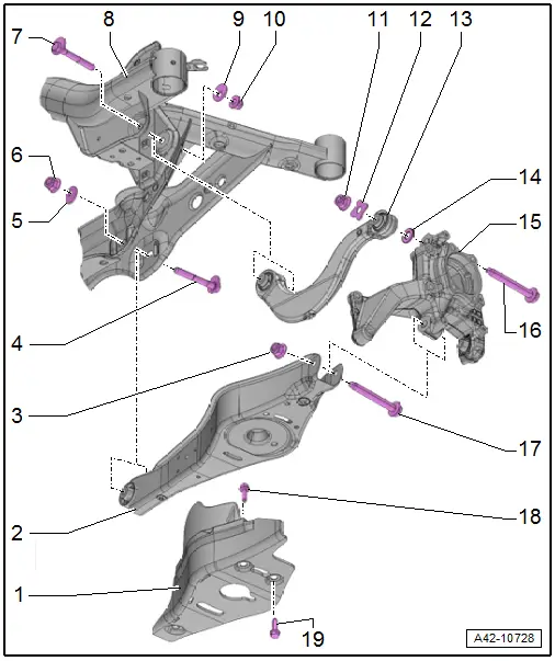
1 - Stone Chip Protection
- For allocation. Refer to the Parts Catalog.
2 - Lower Transverse Link
- Removing and installing. Refer to → Chapter "Lower Transverse Link, Removing and Installing, FWD Vehicles".
3 - Nut
- 90 Nm + 90º
- Always replace if removed
- Always tighten threaded connections in curb weight position. Refer to → Chapter "Wheel Bearing in Curb Weight, Lifting Vehicles with Coil Spring".
4 - Eccentric Screw
- Do not turn more than 90º right or left (that is smallest to largest possible adjustment)
- For toe setting
- Perform a vehicle alignment after loosening. Refer to → Chapter "Axle Alignment Procedure".
5 - Eccentric Washer
- Inner bore with tab
6 - Nut
- 95 Nm
- Always replace if removed
- Always tighten threaded connections in curb weight position. Refer to → Chapter "Wheel Bearing in Curb Weight, Lifting Vehicles with Coil Spring".
7 - Eccentric Screw
- Do not turn more than 90º right or left (that is smallest to largest possible adjustment)
- For camber setting
- Perform a vehicle alignment after loosening. Refer to → Chapter "Axle Alignment Procedure".
8 - Subframe
- Removing and installing. Refer to → Chapter "Subframe, Removing and installing, FWD Vehicles".
9 - Eccentric Washer
- Inner bore with tab
10 - Nut
- 95 Nm
- 80 Nm. This tightening specification only applies in conjunction with Insert Tool - 18mm -T10179-
- Always replace if removed
- Always tighten threaded connections in curb weight position. Refer to → Chapter "Wheel Bearing in Curb Weight, Lifting Vehicles with Coil Spring".
11 - Nut
- For tightening specifications, see bolt -16-
- Always replace if removed
12 - Washer
13 - Upper Transverse Link
- Removing and installing. Refer to → Chapter "Upper Transverse Link, Removing and Installing, FWD Vehicles".
14 - Washer
15 - Wheel Bearing Housing
16 - Bolt
- 130 Nm + 90º
- Always replace if removed
- Always tighten threaded connections in curb weight position. Refer to → Chapter "Wheel Bearing in Curb Weight, Lifting Vehicles with Coil Spring".
17 - Bolt
- Always replace if removed
18 - Expanding Rivet
- Quantity: 2
19 - Bolt
- 8 Nm
- Quantity: 3
Overview - Tie Rod
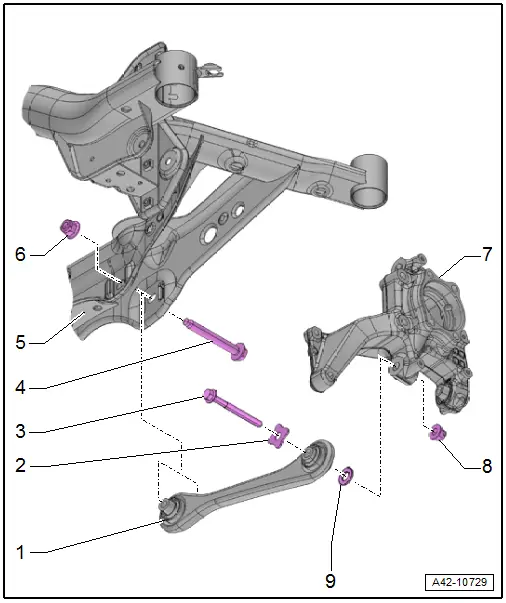
1 - Tie Rod
- Removing and installing. Refer to → Chapter "Tie Rod, Removing and Installing, FWD Vehicles".
2 - Washer
3 - Bolt
- 130 Nm + 90º
- Always replace if removed
- Always tighten threaded connections in curb weight position. Refer to → Chapter "Wheel Bearing in Curb Weight, Lifting Vehicles with Coil Spring".
4 - Bolt
- Always replace if removed
5 - Subframe
- Removing and installing. Refer to → Chapter "Subframe, Removing and installing, FWD Vehicles".
6 - Nut
- 90 Nm + 90º
- Always replace if removed
7 - Wheel Bearing Housing
8 - Nut
- Always replace if removed
9 - Washer
READ NEXT:
 Upper Transverse Link, Removing and Installing
Upper Transverse Link, Removing and Installing, FWD Vehicles
Special tools and workshop equipment
required
Torque Wrench 1332 40-200Nm -VAG1332-
Removing
- Measure dimension from cente
Lower Transverse Link, Removing and Installing
Lower Transverse Link, Removing and Installing, FWD Vehicles
Special tools and workshop equipment
required
Torque Wrench 1332 40-200Nm -VAG1332-
Removing
- Measure dimension from cente
Tie Rod, Removing and Installing
Tie Rod, Removing and Installing, FWD Vehicles
Special tools and workshop equipment
required
Torque Wrench 1331 5-50Nm -VAG1331-
Torque Wrench 1332 40-200Nm -VAG1332-
Removing
- MeasSEE MORE:
Luggage compartment lid
General information
WARNING
Applies to: vehicles with anti-theft alarm
system: When the vehicle is locked from the
outside, no one, especially children, should
remain in the vehicle, because the windows
can no longer open from the inside. Locked
doors make it more difficult for emergency
wor
Drive system
Breaking in
A new vehicle must be broken in within the first
1,000 miles (1,500 km) so that all moving parts
work smoothly together, which helps to increase
the service life of the engine and other drive components.
Do not drive higher than two-thirds of the maximum
permitted engine RPM during the
© 2019-2026 Copyright www.auq3.net | 0.0125
