Audi Q3: Subframe, Servicing
Special tools and workshop equipment required
- Bearing Installer - Wheel Hub/Bearing Kit -T10205-
- Torque Wrench 1332 40-200Nm -VAG1332-
- Hydraulic Press -VAS6178-
- Pneumatic/Hydraulic Foot Pump -VAS6179-
- Hydraulic Press - Bushing Tool Kit -VAS6779-
- Press Plate -VW401-
- Press Piece - Multiple Use -VW412-
Replace the pendulum support bonded rubber bushing.
- Remove the front noise insulation. Refer to → Body Exterior; Rep. Gr.66; Overview - Noise Insulation.
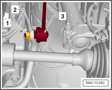
- Remove the hex nut -1- from the right and left coupling rod -3-.
- Remove the coupling rod -3- from the stabilizer bar -2- on the left and right sides.
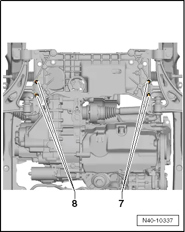
- Remove the stabilizer bolts -7- and -8-.
- Leave the stabilizer bar in the installed position on the vehicle.
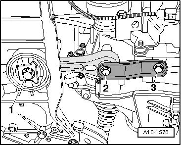
- Remove the bolt -1-.
- Remove the bolts -2- and -3-.
- Remove the pendulum support.
Pressing out the bonded rubber bushing
- Install the Hydraulic Press - Bushing Tool Kit -VAS6779 -as shown in the illustration on the subframe.
- Position the Hydraulic Press - Bushing Tool Kit -Thrust Piece -VAS6779-1--1- with the flat side -arrow- on the bonded rubber bushing in the driving direction.
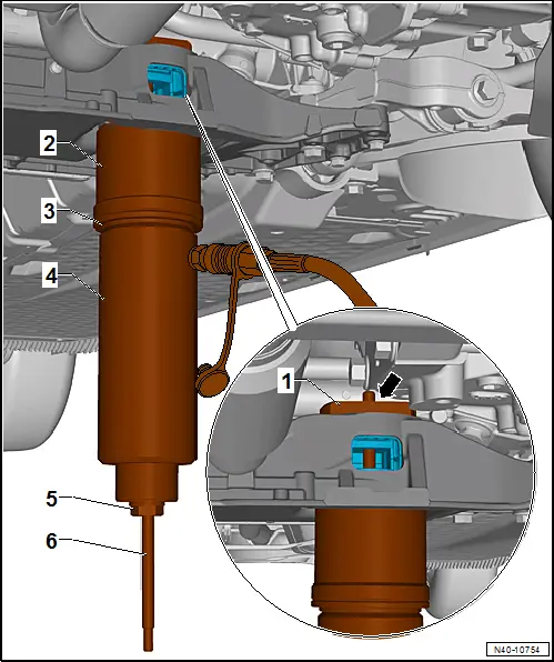
1 - Hydraulic Press - Bushing Tool Kit -Thrust Piece -VAS6779/1-
2 - Hydraulic Press - Bushing Tool Kit -Tube -VAS6779/4-, with the small outer diameter to the sub frame.
3 - Hydraulic Press - Bushing Tool Kit -Thrust Piece -VAS6779/5-
4 - Hydraulic Press -VAS6178- with Bearing Installer - Wheel Hub/Bearing Kit Pressure Head -T10205/13-
5 - Hydraulic Press - Bushing Tool Kit -Hexagon Nut -VAS6779/3-
6 - Hydraulic Press - Bushing Tool Kit -Threaded Rod -VAS6779/2-
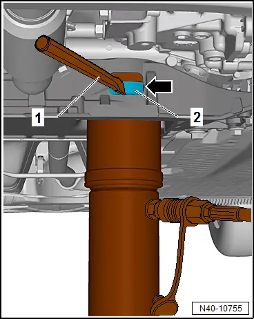
- Press out both bonded rubber bushings until the upper bonded rubber busing -2- is visible through the opening for the pendulum support -arrow- in the subframe.
- Perform a visual inspection of the upper bonded rubber bushing -2- outer race.
- If the upper bonded rubber bushing -2- outer race is deformed, it must be destroyed through the opening for the pendulum support -arrow- in the subframe.
- Using a using a chisel or similar tool -1-, make a break in the upper bonded rubber bushing -2- outer race.
 Note
Note
This work sequence is necessary to prevent tilting of the bonded rubber bushing outer race in the area of the pendulum support opening in the subframe.
- Completely press out both bonded rubber bushings at the same time.
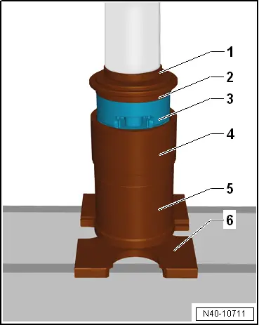
Prepare the bonded rubber bushing before pressing in.
 Note
Note
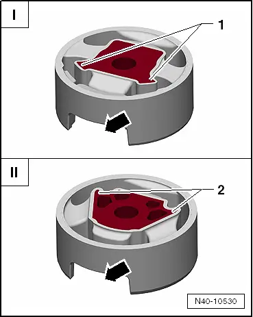
- There are two different versions of the pendulum support bonded rubber bushing: the T version -I- and the V version -II-.
- For the correct allocation. Refer to the Parts Catalog.
I - The corners on the inner core -1- face toward the opening for the pendulum support -arrow- (T version).
II - The corners on the inner core -2- face away from the opening for the pendulum support -arrow- (V version).
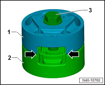
- Place the bonded rubber bushings -1- and -2- on top of each other so the openings -arrows- lay exactly over each other.
- Tighten the bonded rubber bushings -1- and -2- using the original bolt -3- hand tight.
- Place the bonded rubber busing -1- with the bolt head facing up in the larger diameter of the Hydraulic Press - Bushing Tool Kit - Funnel -VAS6779/6--2-.
- Align the bonded rubber busing -1- in the Hydraulic Press - Bushing Tool Kit - Funnel -VAS6779/6--2-. The bonded rubber bushing opening -arrows- must exactly lay in the recess on the Hydraulic Press - Bushing Tool Kit - Funnel -VAS6779/6--2-.
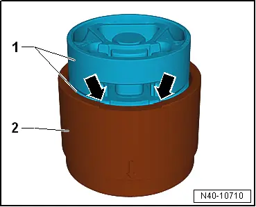
- Press the bonded rubber bushing -3- in the Hydraulic Press - Bushing Tool Kit - Funnel -VAS6779/6- as shown in the illustration until stop.
1 - Press Piece - Multiple Use -VW412-
2 - Hydraulic Press - Bushing Tool Kit -Thrust Piece -VAS6779/5-, the side with the letter "A" points up
3 - Bonded Rubber Bushing
4 - Funnel -VAS6779/6-
5 - Tube -VAS6779/4-
6 - Press Plate -VW401-
- Remove the bolt from the bonded rubber bushing.
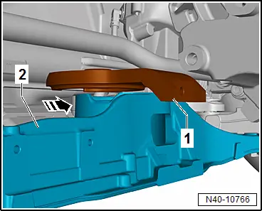
- Place the Hydraulic Press - Bushing Tool Kit-Counter Hold -VAS6779/7--1- front left in the direction of the-arrow- on the subframe -2-.
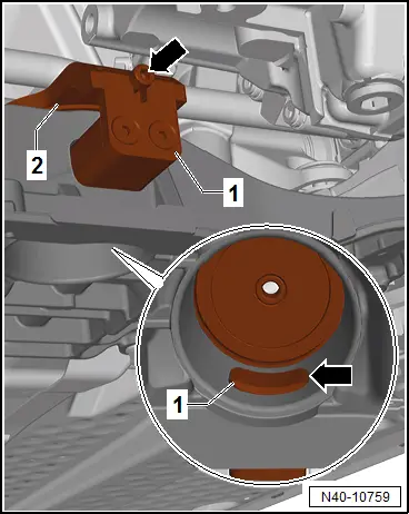
- Insert the Insert -VAS6779/7-1A--1- in the pendulum support opening in the subframe.
- Attach the Insert -VAS6779/7-1A- with the bolt -arrow- on the Hydraulic Press - Bushing Tool Kit-Counter Hold -VAS6779/7--2-.
- Pay attention that the Insert -VAS6779/7-1A--1- is seated correctly in the subframe opening -arrow-.
Installing the bonded rubber bushing
- Install the Hydraulic Press - Bushing Tool Kit -Threaded Rod -VAS6779/2--7- in the Hydraulic Press - Bushing Tool Kit-Counter Hold -VAS6779/7--1-.
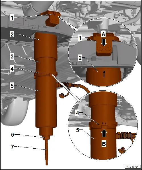
- Install the Hydraulic Press - Bushing Tool Kit -VAS6779- as shown in the illustration on the subframe.
1 - Hydraulic Press - Bushing Tool Kit-Counter Hold -VAS6779/7-
2 - Hydraulic Press - Bushing Tool Kit - Funnel -VAS6779/6-, -arrow marking- on the funnel must be opposite of both bolts -arrow A-.
3 - Hydraulic Press - Bushing Tool Kit - Thrust Piece -VAS6779/9-
4 - Hydraulic Press - Bushing Tool Kit -Incremental Ring -VAS6779/8-, the marking -IIII- on the Incremental Ring must point to the cam -arrow B- on the Hydraulic Press - Bushing Tool Kit -Thrust Piece -VAS6779/9-.
5 - Hydraulic Press -VAS6178- with Bearing Installer - Wheel Hub/Bearing Kit Pressure Head -T10205/13-
6 - Hydraulic Press - Bushing Tool Kit - Hexagon Nut -VAS6779/3-
7 - Hydraulic Press - Bushing Tool Kit - Threaded Rod -VAS6779/2-
- Press in both bonded rubber busing at the same time.
- Remove Hydraulic Press - Bushing Tool Kit -VAS6779- from the subframe and check seating of the pressed in bonded rubber bushing.
- Fasten the stabilizer bar with the subframe and the coupling rod.
- Install the pendulum support.
- Install the front noise insulation. Refer to → Body Exterior; Rep. Gr.66; Overview - Noise Insulation.
Tightening Specifications
- Pendulum support.
READ NEXT:
 Stabilizer Bar, Removing and Installing
Special tools and workshop equipment
required
Locating Pins -T10096-
Torque Wrench 1332 40-200Nm -VAG1332-
Engine and Gearbox Jack -VAS6931-
Puller - Ball Joint -3287A-
Removing
-
Subframe, Securing
Special tools and workshop equipment
required
Locating Pins -T10096-
Torque Wrench 1332 40-200Nm -VAG1332-
Engine and Gearbox Jack -VAS6931-
Procedure
- Remove the noise insulation
Suspension Strut and Upper Control Arm
Overview - Suspension Strut and Upper Control Arm
1 - Shock Absorber
On vehicles with electronically controlled damping, perform the
function "Adapt the control position" with the VSEE MORE:
Lock Cylinder, Removing and Installing
Create an assisting tool from a wire hook as follows:
- Take a 1.5 mm diameter welding wire and bend the end to form
an eye.
- Then cut the welding wire.
Dimension -a- = approximately
50 mm.
- File the end of the wire hook into a point.
Dimension -b- = 3 mm
