Audi Q3: Stabilizer Bar, Removing and Installing
Special tools and workshop equipment required
- Locating Pins -T10096-
- Torque Wrench 1332 40-200Nm -VAG1332-
- Engine and Gearbox Jack -VAS6931-
- Puller - Ball Joint -3287A-
Removing
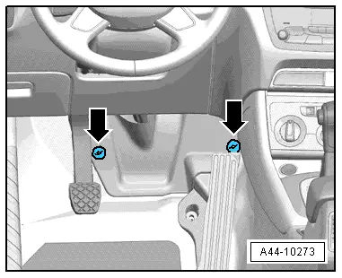
- Remove the footwell trim panel by removing the nuts -arrows-.
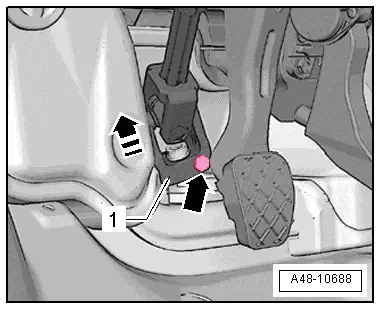
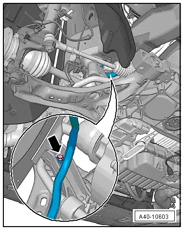
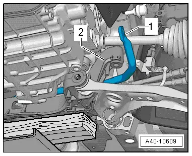
- Remove the bolt -arrow- from the universal joint -1-. Then remove the universal joint from the steering gear in direction of -arrow-.
- Remove the front wheels. Refer to → Chapter "Wheels and Tires".
- Secure the subframe. Refer to → Chapter "Subframe, Securing".
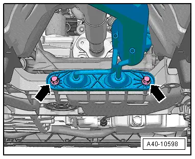
- Remove the bolts -arrows-.
- If installed, remove the Left Front Level Control System Sensor -G78- or Right Front Level Control Sensor -G289-. Refer to → Chapter "Left/Right Front Level Control System Sensor -G78-/-G289-, Removing and Installing".
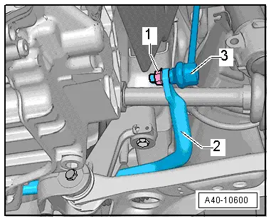
- Remove the left and right nut -1- from the coupling rod -3-.
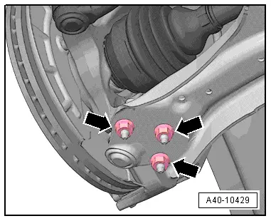
- Remove the nuts -arrows-.
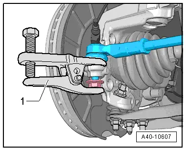
- Loosen the nut of the tie rod end, but do not remove yet.
- Remove the tie rod end from the wheel bearing housing using the Puller - Ball Joint -3287A--1-.
- Remove the stabilizer bar from the subframe by removing the bolts -1 and 4-.
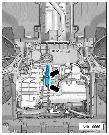
- Remove the bolts -arrows- and then remove the pendulum support from the transmission.
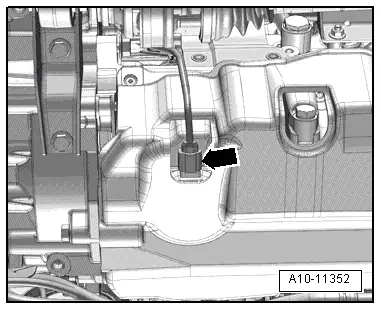
Vehicles with 4-cylinder Engine
- Disconnect the connector for the Oil Level Thermal Sensor -G266--arrow- and free up the wire.
Continuation for All Vehicles
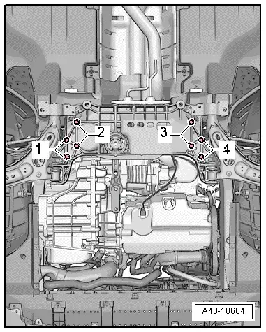
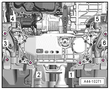
- Loosen the bolts -1- and -2- to slightly lower the subframe. Pay attention the electrical wiring while doing this.
- Remove the cable guide from the subframe -arrow-.
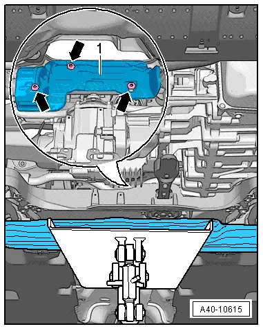
- Lower the subframe until the bolted connections -arrows- on the steering gear heat shield -1- are accessible.
- Remove the bolts -arrows- and the heat shield -1-.
- Slide the stabilizer bar toward the right, as seen in direction of travel.
- Remove the stabilizer bar -1- forward from the subframe over the console -2-.
Installing
Install in reverse order of removal while noting the following:
- Remove the Locating Pins -T10096-.
- Install the subframe with the steering gear. Refer to → Chapter "Subframe with Steering Gear, Removing and Installing".
- Install the front wheels. Refer to → Chapter "Wheels and Tires".
- An axle alignment may be required. Refer to → Chapter "Evaluating Need for Axle Alignment".
Tightening Specifications
- Pendulum support.
- Exhaust system bracket.
Coupling Rod, Removing and Installing
Special tools and workshop equipment required
- Torque Wrench 1331 5-50Nm -VAG1331-
- Torque Wrench 1331 Insert - Ring Wrench - 16mm -VAG1331/12-
Removing
- Remove the front wheel. Refer to → Chapter "Wheels and Tires".
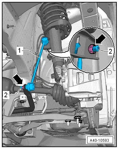
- Remove the nuts -arrows- from the coupling rod -1- by counterholding with a multipoint socket on the threaded pin -2- if necessary.
- Remove the coupling rod -1- from the stabilizer bar and suspension strut.
- Remove the coupling rod -1-.
Installing
Installation is reverse of removal, noting the following:
- Tighten the nuts -arrow- for securing the coupling rod on the suspension strut or stabilizer bar by counterholding with a multipoint socket on the threaded pin -2-.
 Note
Note
The counter hold tool cannot be tilted.
- Install the front wheel.
READ NEXT:
 Subframe, Securing
Special tools and workshop equipment
required
Locating Pins -T10096-
Torque Wrench 1332 40-200Nm -VAG1332-
Engine and Gearbox Jack -VAS6931-
Procedure
- Remove the noise insulation
Suspension Strut and Upper Control Arm
Overview - Suspension Strut and Upper Control Arm
1 - Shock Absorber
On vehicles with electronically controlled damping, perform the
function "Adapt the control position" with the V
Overview - Lower Control Arm and Ball Joint
1 - Control Arm
Control arm with mounting bracket, removing and installing. Refer to
→ Chapter "Lower Control Arm, Removing and Installing".
2 - Bonded Rubber BushSEE MORE:
Mechanically unlocking and locking the doors
All doors must be unlocked or locked separately
if the central locking system fails.
Fig. 22 Driver's door: door lock cylinder
Fig. 23 Door: mechanically locking
Applies to: vehicles with anti-theft alarm system:
After unlocking using the lock cylinder and opening
the driver's door, you must press
High beam assistant
Applies to: vehicles with high beam assistant
The high beam assistant automatically turns the
high beams on or off depending on the surrounding
conditions.
A camera on the rearview mirror mount can detect
light sources from other road users. The high
beams switch on or off automatically depending
o