Audi Q3: Subframe, Securing
Special tools and workshop equipment required
- Locating Pins -T10096-
- Torque Wrench 1332 40-200Nm -VAG1332-
- Engine and Gearbox Jack -VAS6931-
Procedure
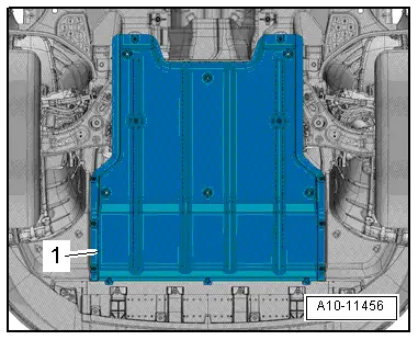
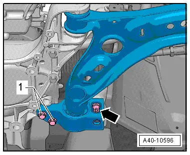
- Remove the noise insulation -1-. Refer to → Body Exterior; Rep. Gr.66; Noise Insulation; Noise Insulation, Removing and Installing.
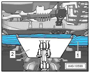
- Position the Engine and Gearbox Jack -VAS6931--2- under the subframe.
- Place, for example, a block of wood -1- between the Engine and Gearbox Jack -VAS6931- and the subframe.
- Clean the locking pin threads if necessary.
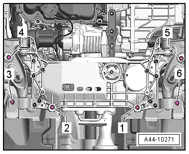
To secure the subframe, the Locating Pins -T10096- must be installed at the positions -3 through 6- one after the other.
- The items -4- and -5- must be secured first.
 Note
Note
The locating pins may only be tightened to a maximum of 20 Nm, since otherwise the locating pin threads will be damaged.
Subframe, Securing
 Caution
There is a risk of damaging the subframe threaded connection threads on the body.
- The subframe bolts on the body must not be loosened or tightened with an impact wrench.
- Always install all bolts by hand for the first few turns.
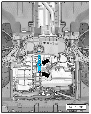
- Replace the bolt one after another on both sides of the vehicle with the Locating Pins -T10096--arrows- and tighten to 20 Nm.
Securing mounting bracket
 Caution
There is a risk of damaging the subframe threaded connection threads on the body.
- The subframe bolts on the body must not be loosened or tightened with an impact wrench.
- Always install all bolts by hand for the first few turns.
- Replace the bolt one after another on both sides of the vehicle with the Locating Pins -T10096--arrows- and tighten to 20 Nm.
- Securing the subframe is completed when all above mentioned bolts are replaced with Locating Pins -T10096- one after the other.
- Position of front axle is now secured.
Remove the Locating Pins -T10096-.
The removal is reverse of installation, noting the following:
- Always only remove one locating pin and replace it with a new bolt.
After installation, position of steering wheel must be checked with a road test.
- An axle alignment may be required. Refer to → Chapter "Evaluating Need for Axle Alignment".
Subframe, Lowering
Special tools and workshop equipment required
- Locating Pins -T10096-
- Torque Wrench 1332 40-200Nm -VAG1332-
- Engine and Gearbox Jack -VAS6931-
Removing
- Turn the steering wheel to the straight-ahead position and remove the ignition key so that the steering wheel lock engages.
Vehicles with "Keyless Access Authorization System"
- Switch the ignition off and open the driver door so the steering wheel lock locks.
Continuation for All Vehicles
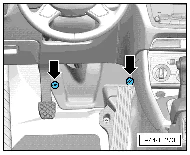
- Remove the footwell trim panel by removing the nuts -arrows-.
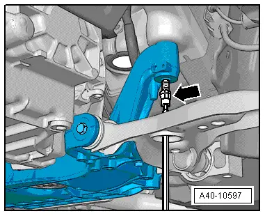
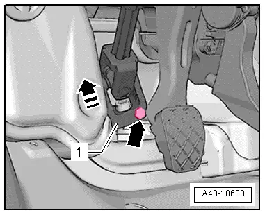
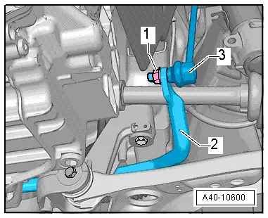
- Remove the bolt -arrow- from the universal joint -1-. Then remove the universal joint from the steering gear in direction of -arrow-.
- Secure the subframe. Refer to → Chapter "Subframe, Securing".
- Remove the bolts -arrows-.
- Remove the bolts -arrows- and then remove the pendulum support from the transmission.
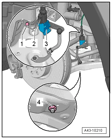
- Remove the left and right nut -1- from the coupling rod -3-.
- Remove the coupling rod -3- from the stabilizer bar -2- on the left and right sides.
- If installed, disconnect the connector -2- from the Left Front Level Control System Sensor -G78- or Right Front Level Control Sensor -G289-.
- Remove the nut -4- and free up the coupling rod from the Left Front Level Control System Sensor -G78- or Right Front Level Control Sensor -G289-.
Vehicles with 4-cylinder Engine
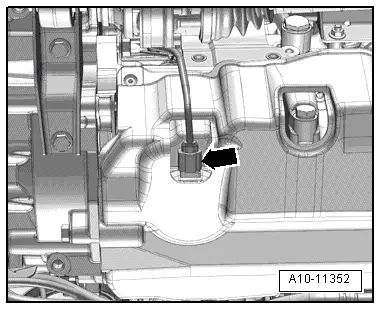
- Disconnect the connector for the Oil Level Thermal Sensor -G266--arrow- and free up the wire.
Continuation for all vehicles
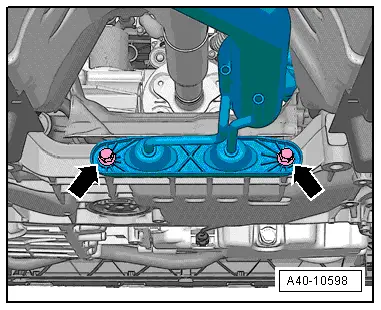
- Remove the remaining bolts -1- and -2- and lower the subframe maximum 10 cm.
 Note
Note
Be careful not to overstretch the wire for the steering and the Oil Level Thermal Sensor -G266-.
Installing
Install in reverse order of removal while noting the following:
- Remove the Locating Pins -T10096-.
- An axle alignment may be required. Refer to → Chapter "Evaluating Need for Axle Alignment".
- On vehicles with electronically controlled damping, perform the function "Adapt the control position" with the Vehicle Diagnostic Tester.
- If the control position was reprogrammed and if the vehicle has lane assist, then it will then be necessary to calibrate the driver assistance systems front camera. Refer to → Chapter "Driver Assistance Systems Front Camera, Calibrating".
- On vehicles with level control system sensor, perform headlamp basic setting. Refer to → Electrical Equipment; Rep. Gr.94; Headlamp, Adjusting.
Tightening Specifications
- Pendulum support.
- Exhaust system bracket.

READ NEXT:
 Suspension Strut and Upper Control Arm
Overview - Suspension Strut and Upper Control Arm
1 - Shock Absorber
On vehicles with electronically controlled damping, perform the
function "Adapt the control position" with the V
Overview - Lower Control Arm and Ball Joint
1 - Control Arm
Control arm with mounting bracket, removing and installing. Refer to
→ Chapter "Lower Control Arm, Removing and Installing".
2 - Bonded Rubber Bush
Lower Control Arm, Removing and Installing
Special tools and workshop equipment
required
Locating Pins -T10096-
Torque Wrench 1332 40-200Nm -VAG1332-
Removing
- Before starting work, determine the measurement
-a-, for example
SEE MORE:
General information
Park the vehicle as far as possible from moving
traffic in the event of a breakdown. In the event
of a flat tire, park the vehicle on a level surface.
If you are on a steep hill, be especially careful.
Set the parking brake.
Switch the emergency flashers on.
Have the passengers exit the vehi
Infotainment System Display, Removing and Installing
Infotainment System Display, Removing and Installing
The Front Information Display Control Head -J685- (Display)
is located in the center of the instrument panel.
The display and display support are a single unit and are
removed together. After its removal the display is removed from
the dis
