Audi Q3: Battery Interrupt Igniter
Overview - Battery Interrupt Igniter
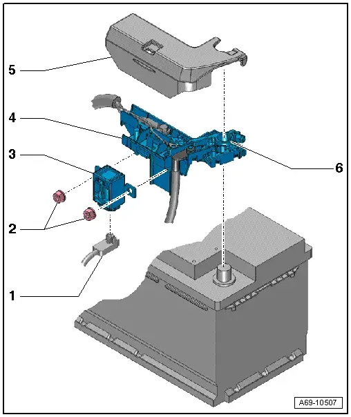
1 - Connector
- For the Battery Interrupt Igniter -N253-
- Releasing and removing
2 - Nuts
- 15 Nm
3 - Battery Interrupt Igniter -N253-
- Available only together with -4-
- Removing and installing. Refer to → Chapter "Battery Interrupt Igniter, Removing and Installing".
4 - Fuse Panel A -SA-
5 - Cover
- For Fuse Panel A -SA-
6 - Positive Terminal Clamp
- Tightening specification. Refer to → Electrical Equipment; Rep. Gr.27; Battery; Overview - Battery.
Battery Interrupt Igniter, Removing and Installing
Special tools and workshop equipment required
- Vehicle Diagnostic Tester
Removing
 WARNING
- Follow all safety precautions when working with pyrotechnic components. Refer to → Chapter "Pyrotechnic Components Safety Precautions".
- Follow all regulations when disposing of pyrotechnic components. Refer to → Chapter "Airbag, Belt Tensioner and Battery Cut-Out Units, Storing, Transporting and Disposing".
 Note
Note
- If Airbag Indicator Lamp -K75- comes on after a vehicle accident, check whether crash data is stored using → Vehicle diagnostic tester. If this is the case, check if the malfunction "Resistance too high" for the Battery Interrupt Igniter -N253- is stored in the DTC memory. If this is the case, Battery Interrupt Igniter -N253- must be replaced.
- The Battery Interrupt Igniter -N253- interrupts the electrical circuit each time an airbag is deployed. The Battery Interrupt Igniter -N253- must be replaced after a deployment.
- The Battery Interrupt Igniter -N253- is available as a replacement part only together with Fuse Panel A -SA-.
- When just replacing the battery interrupt igniter -N253-, remove it from the replacement part and install it in Fuse Panel A -SA- as follows.
- Switch the ignition on.
- Disconnect the battery ground cable with the ignition turned on. Refer to → Electrical Equipment; Rep. Gr.27; Battery; Battery, Disconnecting and Connecting.
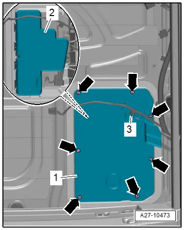
- Remove the bolts -arrows-.
- Free up the wiring harness -3-, if equipped.
- Remove the cover -1- for the battery.
- Remove the heat shield -2- from the battery.
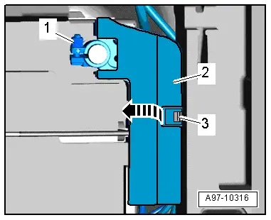
- Loosen the nut -1- several turns and remove the battery positive cable terminal with Fuse Panel A -SA- from the battery terminal.
- Remove Fuse Panel A -SA-.
- Release the spring -3- and open the flap -2- overFuse Panel A -SA--arrow-.
 WARNING
Before handling pyrotechnic components (for example, disconnecting the connector), the person handling it must "discharge static electricity". This can be done by touching the door striker, for example.
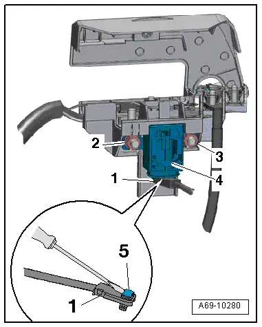
- Remove the nuts -2 and 3-.
- Remove battery interrupt igniter -4-.
- To do this, open the connector lock -5- using a small screwdriver and disconnect the connector -1-.
Installing
 WARNING
- Follow all safety precautions when working with pyrotechnic components. Refer to → Chapter "Pyrotechnic Components Safety Precautions".
- Before handling pyrotechnic components (for example, connecting the connector), the person handling it must "discharge static electricity". This can be done by touching the door striker, for example.
Install in reverse order of removal. Note the following:
 Note
Note
Make sure the connectors are installed correctly and are secure.
 WARNING
Ignition must be on when connecting battery. If pyrotechnic components (for example, airbag, belt tensioner) are not repaired correctly, they may deploy unintentionally after connecting battery. There must not be anyone inside the vehicle when connecting the battery.
- Connect the battery ground cable with the ignition turned on. Refer to → Electrical Equipment; Rep. Gr.27; Battery; Battery, Disconnecting and Connecting.
- Check the DTC memory for the Airbag Control Module -J234- and correct any entries if necessary using the Vehicle Diagnostic Tester → Vehicle diagnostic tester.
Installation notes, for example tightening specifications, replacing components. Refer to → Chapter "Overview - Battery Interrupt Igniter".
READ NEXT:
 Driver Side Airbag
Overview - Driver Side Airbag
1 - Locking Bracket
Use a T25 TORX screwdriver, approximately 100 mm long
2 - Steering Column Electronics Control Module -J527-
With Air
Front Passenger Airbag
Overview - Front Passenger Airbag
1 - Front Passenger Airbag
With Front Passenger Airbag Igniter 1 -N131-
WARNING
Follow all safety precautions when working with pyro
Side Airbags
Overview - Front Side Airbag
1 - Backrest Frame
2 - Hook
For securing the side airbag to the backrest frame
3 - Front Side Airbag
Driver side: with the DriSEE MORE:
Trailer Hitch
Overview - Trailer Hitch Socket and Towing Recognition Control Module
1 - LED Indicator Lamp
Trailer Hitch -Locked- Indicator Lamp -K226-, Trailer Hitch
-Unlocked- Indicator Lamp -K227-
Make sure the trailer hitch is locked correctly
Removing and installing. Refer to
→&nbs
Antenna Wires, Repairing
Aerial Cable Repair Set VAS6720
Special tools and workshop equipment
required
Aerial Cable Repair Set -VAS6720-
The Aerial Cable Repair Set -VAS6720- makes it possible to
perform a quality repair on antenna wires RG 174 (blue) and RTK
031 (black). The set contains the insulation remova