
Audi Q3: Overview - Lower Control Arm and Ball Joint
Suspension, Wheels, Steering / Chassis / Audi Q3 (8U) 2011-2018 Service Manual / Overview - Lower Control Arm and Ball Joint
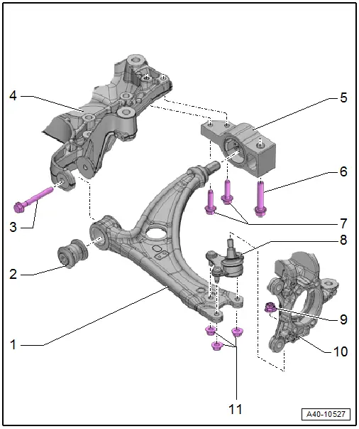
1 - Control Arm
- Control arm with mounting bracket, removing and installing. Refer to → Chapter "Lower Control Arm, Removing and Installing".
2 - Bonded Rubber Bushing
- Replacing. Refer to → Chapter "Lower Control Arm Bonded Rubber Bushing, Replacing".
3 - Bolt
- 70 Nm + 180º
- Always replace if removed
- Tighten only in curb weight position. Refer to → Chapter "Wheel Bearing in Curb Weight, Lifting Vehicles with Coil Spring".
4 - Subframe
5 - Mounting Bracket
- Securing.
6 - Bolt
- 70 Nm + 180º
- Always replace if removed
7 - Bolts
- 50 Nm + 90º
- Always replace if removed
8 - Ball Joint
- Removing and installing. Refer to → Chapter "Ball Joint, Removing and Installing".
9 - Nut
- 60 Nm
- Always replace if removed
- Counterhold at socket head of joint bolt when tightening
10 - Wheel Bearing Housing
- Removing and installing. Refer to → Chapter "Wheel Bearing Housing, Removing and Installing".
11 - Nut
- 100 Nm
- Always replace if removed
READ NEXT:
 Lower Control Arm, Removing and Installing
Special tools and workshop equipment
required
Locating Pins -T10096-
Torque Wrench 1332 40-200Nm -VAG1332-
Removing
- Before starting work, determine the measurement
-a-, for example
Ball Joint, Removing and Installing
Special tools and workshop equipment
required
Puller - Ball Joint -3287A-
Digital Torque Wrench -VAG1756A-
Torque Wrench 1332 Insert - Ring Wrench - 18mm -VAG1332/10-
Removing
- Loo
Overview - Wheel Bearing
1 - Suspension Strut
2 - Bolt
70 Nm + 90º
Always replace if removed
Bolt point must face in direction of travel.
3 - Front Speed Sensor
Removing and inSEE MORE:
Hinges, Removing and Installing
1 - Hood Hinge
Removing
Before removing a hood hinge, support the hood or secure it against
falling.
Remove the gas-filled strut. Refer to
→ Chapter "Gas-Filled Strut, Removing and Installing".
Unclip and remove the cover from the lid hinges.
Remove the bolts -
Wheel Electronics, New Design
Assembly Sequence
- Fold the valve -1- downward
-arrow A toward B-.
- Slide the valve with the wheel electronics attached through
the valve opening in the rim.
- Rotate the union nut -2- three
turns on the valve -1-.
- Tighten the union nut -2- until
the bar breaks w
© 2019-2026 Copyright www.auq3.net | 0.0102
