Audi Q3: Repair Information
Shock Absorber Leaks
Shock absorbers are frequently rejected and exchanged because of leaks. Examinations on the test stand and on the vehicle have shown that the replacement of a large number of rejected shock absorbers was not justified.
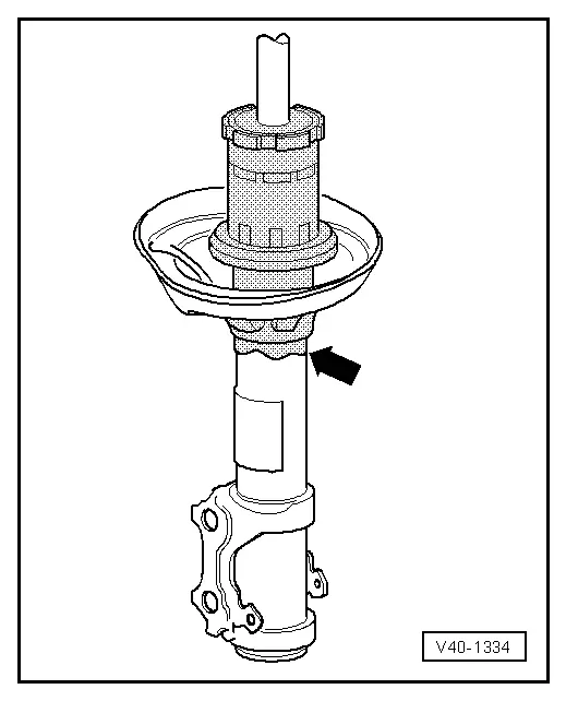
Slight leaking of oil ("sweating") at piston rod seal is no reason to replace a shock absorber. A shock absorber damp with oil is OK under the following circumstances:
- Oil leak (shown screened in illustration) is visible, but dull, matte and possibly dry from dust
- Oil excretion extends from upper shock absorber connection (piston rod oil seal) no further than lower spring plate -arrow-
Shock Absorbers, Checking when Removed
Defective shock absorbers are noticeable when driving due to loud rumbling noises - a result of wheel hopping - especially on poor stretches of road. Moreover, they can be recognized by a large loss of oil.
 Note
Note
Shock absorbers are maintenance-free, shock absorber oil cannot be topped off.
A removed shock absorber can be checked by hand as follows:
- Push the shock absorber together by hand.
- Piston rod must move with even resistance throughout entire stroke and without jerking.
- Release piston rods.
- For shock absorbers with sufficient gas pressure, piston rod returns to initial position automatically.
 Note
Note
- If this is not the case, shock absorber must be replaced. As long as oil loss is not large, the effectiveness represents that of a conventional shock absorber.
- The damping function is also completely available without gas pressure, as long as there is no large loss of oil. However, noise may increase.
Shock Absorbers, Checking on Shock Tester
Shock absorbers can be checked while installed using the shock tester (shock absorber testing device). The damping effect can be evaluated based on the dial reading or print-out.
Special tools and workshop equipment required
- Maha Shock Absorber Tester -VAS1990- or
- Suspension Strut Test Bed -VAS6636- or
- Suspension Strut Test Bed VAS6640 -VAS6640-
Test Prerequisites
- Temperature +10 through +40 ºC (+50 through +104 ºF).
- Driver in vehicle.
- Tire pressure OK.
- Drive vehicle straight onto center of wheel contact plates.
- Front wheels in straight position.
- Parking not engaged, foot brake not activated.
Threshold
Shock absorber condition can only be judged as follows:
- Sufficient damping effect
or
- Insufficient damping effect
 Note
Note
- Intermediate values for reduced damping performance cannot be read out.
- A prognosis on service life is not permitted.
- Measured values that occur with the involvement of the suspension travel end stops are incorrect.
The following values apply only to the test stands named above. If the specified values are exceeded, the shock absorber action has weakened enough that a replacement is recommended.
Example:
Threshold = 70
- a = greater than 70: insufficient damping effect
- a = less than 70: sufficient damping effect
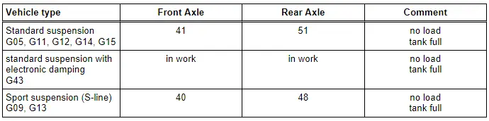
The shock absorber combination installed in the vehicle is indicated by the corresponding PR number on the vehicle data plate.
Production Control Number (PR number) explanation. Refer to → Chapter "Explanations of Production Control Numbers (PR Number)".
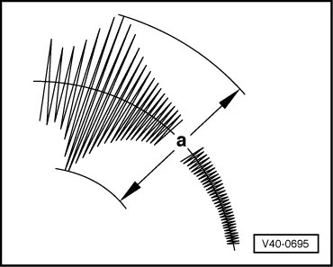
Threshold "a" in mm
 Note
Note
- If the readout value is greater than the limit value "a" (table value): insufficient damping effect ⇒ replace shock absorber.
- If the readout value is less than the limit value "a" (table value): sufficient damping effect ⇒ shock absorber does not need to be replaced.
The tires must be "partially loaded" when measuring the tire pressure.
Clean Working Conditions
- Thoroughly clean connecting points and their surrounding areas before loosening.
- When installing steering gear, make sure centering sleeves are correctly seated between console and steering gear.
- Place removed parts on a clean surface and cover them so that they do not get dirty. Use foil and paper. Only use lint-free cloths!
- Install only clean parts: remove the replacement parts from their packaging just before installing them.
- Use exclusively lubricants and sealants marked with part numbers.
- Carefully cover or seal opened components if the repair will not be done immediately.
General Information
 WARNING
If vehicle will be driving on the streets, all screws and nuts must be tightened properly!
- When installing waxed components, contact surfaces must be cleaned. Contact surfaces must be free of wax and grease.
- Tightening specifications for non-lubricated bolts and nuts are given.
- Always replace self-locking nuts and bolts.
- Always replace the bolts and nuts, which are tightened with an additional tightening angle.
- Welding or straightening operations are not permitted on load-bearing or wheel-controlling components.
- Always avoid the following actions with coil springs: hammer strokes, welding beads, applying color identification later.
- Do not perform any welding or grinding (separating work) in coil spring or suspension strut area! Cover coil spring or suspension struts if necessary.
- When loosening, removing or installing hydraulic, pneumatic or electrical line, always make a sketch or take a picture. This ensures installation is the same as the original.
- If the cable ties, brackets or mounting elements were removed during the repair procedure, they must be installed at their original location.
- Lightly coat the splines on the outer joint with assembly paste before installing the outer joint into the wheel hub. Refer to the Parts Catalog.
- Never allow the drive axle just to hang loose under the vehicle or to bend them at the joints.
- Vehicles without a drive axle must not be moved, otherwise the wheel bearing will be damaged. If a vehicle must be moved, be sure to note the following:
- Install an outer joint in place of the drive axle.
- Tighten the outer joint to 200 Nm.
- Bonded rubber bushings have a limited range of motion. For this reason only tighten threaded connections at control arms if vehicle is in curb weight position. Refer to → Chapter "Wheel Bearing in Curb Weight, Lifting Vehicles with Coil Spring".
- Always replace bonded rubber bushings on both sides of vehicle.
General Repair Information
A number of generally applicable instructions for individual repair operations, which are otherwise mentioned at various points in the Workshop Manual, are summarized here. They apply to this repair manual.
- Before performing repairs on the electro-mechanical steering gear, determine the cause of the damage as accurately as possible using the Vehicle Diagnosis Tester in the "Guided Fault Finding", "Vehicle Self-Diagnosis" and "Measurement" modes.
Contact Corrosion
Contact corrosion can occur if incorrect fasteners (such as bolts, nuts, washers, etc.) are used.
For this reason, only fasteners with a special surface coating are installed.
In addition, rubber or plastic parts and adhesives are made of non-conductive materials.
If there are doubts whether a part should be used again, install a new part according to the Parts Catalog.
Please note:
- The use of original replacement parts is recommended, they are tested and are compatible with aluminum.
- The use of Audi accessories is recommended.
- Damage due to contract corrosion is not covered under warranty!
Steering Gear
To perform a problem-free and successful steering gear repair, extreme caution and cleanliness, as well as properly functioning tools are an important requirement. The usual basic safety precautions also, naturally apply when carrying out vehicle repairs.
Seals, Sealing Rings
- Always replace seals and gaskets.
- After removing seals, inspect contact surface on housings and shafts for burrs and damage and repair if necessary.
- Remove all residual sealant of fluid seals from sealing surfaces, no sealant residue must enter the steering gear housing when doing this.
Bolts and Nuts
- Loosen and tighten the screw and nut from the covers and housings diagonally.
- Do not cant but loosen and tighten especially sensitive parts in diagonal manner in stages, for example servo motor with control module.
- Tightening specifications for non-lubricated bolts and nuts are given.
- Always replace self-locking nuts and bolts.
- Always replace the bolts and nuts, which are tightened with an additional tightening angle.
Electrical Components
Surely everyone has been shocked at one time or another when coming into contact with a metal object. The reason for this is the build-up of static electricity in the human body. This charge can lead to functional problems by touching the electrical components of steering gear.
- Touch a grounded object, such as a water pipe or a vehicle hoist, before working on electrical components. Do not make direct contact on connector terminals.
Damaged Threads in Longitudinal Member, Repairing (Subframe to Body)
For the procedure for repairing a damaged thread.
Wheel Bearing in Curb Weight, Lifting Vehicles with Coil Spring
Special tools and workshop equipment required
- Tensioning Strap -T10038-
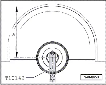
- Engine/Gearbox Jack Adapter - Wheel Hub Support -T10149-
- Engine and Gearbox Jack -VAS6931-
 Note
Note
All bolts at suspension parts with bonded rubber bushings must always be tightened in curb weight position (unloaded condition).
- Bonded rubber bushings have a limited range of motion.
- Axle components with bonded rubber bushings must be brought into the position they will be in during driving before tightening (curb weight position).
- Otherwise, the bonded rubber bushing will be stressed resulting in a shortened service life.
- By raising appropriate suspension using Engine and Gearbox Jack -VAS6931- and Engine/Gearbox Jack Adapter - Wheel Hub Support -T10149-, this position can be simulated on the hoist.
- Before starting work, determine the measurement -a-, for example with tape measure, from center of wheel to lower edge of wheelhouse.
- Measurement must be performed in curb weight position (unloaded condition).
- Note the measured values. It will be required for tightening bolts/nuts.
Before appropriate suspension is raised, vehicle must be strapped to lift arms of hoist using Tensioning Strap -T10038-.
 Note
Note
The vehicle could fall off the hoist if it is not secured.
- Turn the wheel hub until one of the holes for the wheel bolts is on top.
- Install Engine/Gearbox Jack Adapter - Wheel Hub Support -T10149- with wheel bolt on wheel hub.
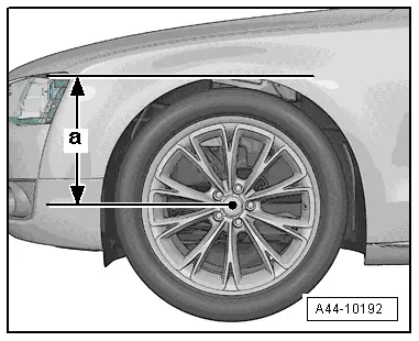
- Lift the wheel bearing housing using the Engine and Gearbox Jack -VAS6931- until dimension -a- is reached.
Tightening of the respective bolts/nuts must only occur if dimension -a-, measured before installation between wheel hub center and lower edge of wheel house, has been attained.
 WARNING
- Do not lift or lower vehicle with the engine/transmission jack still under the vehicle.
- Do not leave the Engine and Gearbox Jack -VAS6931- under the vehicle any longer than necessary.
- Tighten the bolts and nuts.
- Lower the wheel bearing housing.
- Move the engine and gearbox jack away from under vehicle.
- Remove the Engine/Gearbox Jack Adapter - Wheel Hub Support -T10149-
READ NEXT:
 Disposal
Front Shock Absorbers, Venting and Emptying
Method A - Venting through Drill Holes
- Secure gas-filled shock absorber vertically in vise, with
piston rod facing down.
WARNING
Wear
Overview - Subframe
Caution
There is a risk of damaging the subframe threaded
connection threads on the body.
The subframe bolts on the body must not be loosened
or tightened with an impact wrench.
ASEE MORE:
Release Cable, Removing and Installing
Release Cable Coupling
- Remove clips -1- and lift the release
cables -8- and -9-
on both sides toward the hood latches.
- To remove the coupling -2-, release the
retainers -arrows- on the front of the lock
carrier -3- and push them to the rear out
of the bracket.
- Eng
Rear Brake Caliper, Removing and Installing
Brake Caliper, Removing and Installing, Brake 1KU
Note
In the following description the brake caliper is removed
with the brake carrier and pads. The brake hose remains
connected.
Special tools and workshop equipment
required
Torque Wrench 1332 40-200Nm -VAG1332-
Removing
