Audi Q3: Overview - Subframe
Suspension, Wheels, Steering / Chassis / Audi Q3 (8U) 2011-2018 Service Manual / Overview - Subframe
 Caution
There is a risk of damaging the subframe threaded connection threads on the body.
- The subframe bolts on the body must not be loosened or tightened with an impact wrench.
- Always install all bolts by hand for the first few turns.
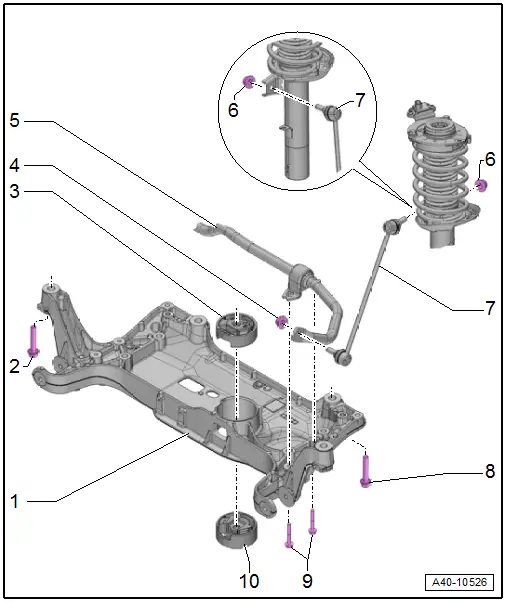
1 - Subframe
- Securing. Refer to → Chapter "Subframe, Securing".
- Lowering. Refer to → Chapter "Subframe, Lowering".
- Removing and installing without steering gear. Refer to → Chapter "Subframe without Steering Gear, Removing and Installing".
- Removing and installing with steering gear. Refer to → Chapter "Subframe with Steering Gear, Removing and Installing".
2 - Bolt
- 70 Nm +180º
- Always replace if removed
3 - Upper Bonded Rubber Bushing for Pendulum Support
- Replacing. Refer to → Chapter "Subframe, Servicing".
4 - Nut
- 65 Nm
- Always replace if removed
- Counterhold at socket head of joint bolt when tightening
5 - Stabilizer Bar
- Removing and installing. Refer to → Chapter "Stabilizer Bar, Removing and Installing".
6 - Nut
- 65 Nm
- Always replace if removed
- Counterhold at socket head of joint bolt when tightening
7 - Coupling Rod
- Removing and installing. Refer to → Chapter "Coupling Rod, Removing and Installing".
8 - Bolt
- 70 Nm +180º
- Always replace if removed
9 - Bolts
- 20 Nm +90º
- Always replace if removed
10 - Lower Bonded Rubber Bushing for Pendulum Support
- Replacing. Refer to → Chapter "Subframe, Servicing".
READ NEXT:
 Subframe without Steering Gear, Removing and Installing
Special tools and workshop equipment
required
Torque Wrench 1331 5-50Nm -VAG1331-
Torque Wrench 1332 40-200Nm -VAG1332-
Engine and Gearbox Jack -VAS6931-
Removing
Note
Subframe
Subframe, Servicing
Special tools and workshop equipment
required
Bearing Installer - Wheel Hub/Bearing Kit -T10205-
Torque Wrench 1332 40-200Nm -VAG1332-
Hydraulic Press -VAS6178-
Pneumatic/Hydraulic Foot Pu
Stabilizer Bar, Removing and Installing
Special tools and workshop equipment
required
Locating Pins -T10096-
Torque Wrench 1332 40-200Nm -VAG1332-
Engine and Gearbox Jack -VAS6931-
Puller - Ball Joint -3287A-
Removing
- SEE MORE:
Engine oil temperature indicator
Applies to: vehicles with engine oil temperature indicator
Depending on the vehicle equipment, the engine
oil temperature may be indicated by
a bar in
the instrument cluster.
Open the vehicle functions tab.
When engine oil temperatures are low, the display
--- ºF (--- ºC) appears in the instr
Unlocking and locking the vehicle
Fig. 26 Door handle: sensor for locking the vehicle
Depending on the vehicle equipment, you may
have various options for unlocking and locking
your vehicle. The settings in the MMI specify
which doors will unlock.
Unlocking or locking using the vehicle key
buttons
To unlock the vehicle, press the
© 2019-2026 Copyright www.auq3.net | 0.0128
