Audi Q3: Rear Bumper Cover, Removing and Installing
 Caution
If the vehicle has lane change assistance, the lane change assistance control module -J769-/-J770- must be recalibrated. Refer to → Electrical Equipment; Rep. Gr.96; Lane Change Assistance; Lane Change Assistance, Calibrating.
Special tools and workshop equipment required
- Body Socket -T40078-
- Hook Tool -T40207-
Removing
- Vehicles with parking aid, lane change assistance, and trailer hitch: Remove the cover from the luggage compartment right side trim panel. Refer to → Body Interior; Rep. Gr.70; Luggage Compartment Trim Panel; Overview - Luggage Compartment Side Trim Panel.
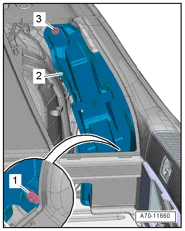
- Remove the vehicle tools.
- Remove the nuts -1 and 3-.
- Remove the vehicle tool kit mount -2-.
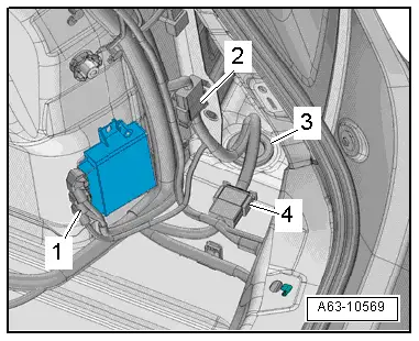
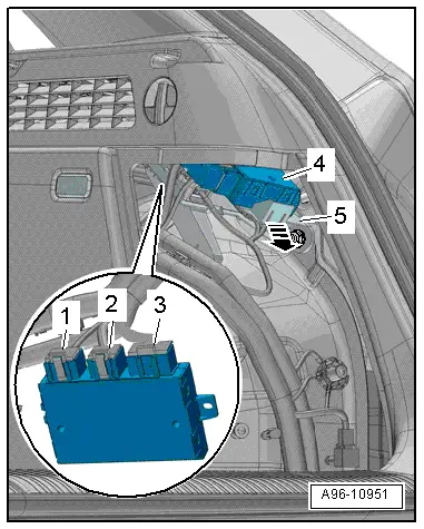
- Disconnect the connector -1- from the Parking Aid Control Module -J446-.
- Disconnect the connectors -2 through 4-.
- Press the grommet -3- outward.
- Remove the lock carrier trim panel. Refer to → Body Interior; Rep. Gr.70; Luggage Compartment Trim Panels; Lock Carrier Trim Panel, Removing and Installing.
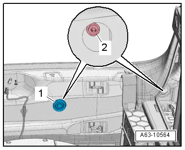
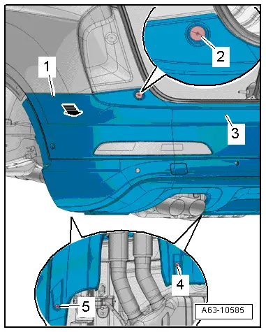
- Remove the grommet -1-.
- Remove the nut -2- with Body Socket -T40078-.
- Remove the rear wheel cover. Refer to → Chapter "Rear Wheel Cover, Removing and Installing".
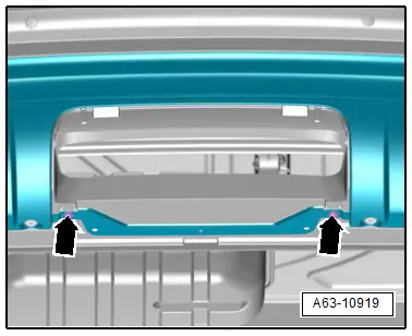
- Vehicles with offroad-equipment: Remove the trailer hitch cover and remove the bolts -arrows-.
- Remove the bolts -2, 4 and 5-.
- Disengage the side bolster -1- on the side panel outward -arrow-.
- Remove the bumper cover -3-.
- If equipped, the wiring harness for the parking aid sensor/lane change assistance control module, trailer hitch must be guided out through the opening in the body.
- Lay the bumper cover on a soft surface.
Installing
Install in reverse order of removal. Note the following:
- Install the rear wheel cover. Refer to → Chapter "Rear Wheel Cover, Removing and Installing".
- Connect the connectors.
- Install the rear lid end trim panel. Refer to → Body Interior; Rep. Gr.70; Luggage Compartment Trim Panel; Overview - Luggage Compartment Side Trim Panel.
- If the vehicle has lane change assistance, the lane change assistance control module -J769-/-J770- must be recalibrated. Refer to → Electrical Equipment; Rep. Gr.96; Lane Change Assistance; Lane Change Assistance, Calibrating.
Impact Member, Removing and Installing
Impact Member, Removing and Installing, Vehicles without Trailer Hitch
Removing
- Remove the rear bumper cover. Refer to → Chapter "Bumper Cover, Removing and Installing".
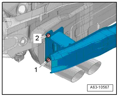
- Remove the bolts -1 and 2-.
- Remove the impact member.
Installing
Install in reverse order of removal. Note the following:
- Install the rear bumper cover. Refer to → Chapter "Bumper Cover, Removing and Installing".
Impact Member, Removing and Installing, Vehicles with Trailer Hitch
Removing
- Remove the cable mount. Refer to → Chapter "Cable Mount, Removing and Installing".
- Remove the rear bumper cover. Refer to → Chapter "Bumper Cover, Removing and Installing".
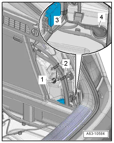
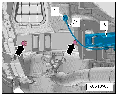
- Open the clip -arrow-.
- Remove the control module -4- from the frame -5-.
- Disconnect the connector -3-.
 Note
Note
Ignore -items 1 and 2-.
- Remove the nut -1- and free up the ground cable.
- Open the cable holders -2 and 3- to free up the wiring harness.
- Push the grommet -4- outward.
- Remove the bolts -arrows-.
- Remove the impact member -3- with a second technician.
- Remove the grommet -2- and guide the cable -1- out.
- If replacing the impact member, remove the trailer hitch socket. Refer to → Electrical Equipment General Information; Rep. Gr.96; Trailer Hitch.
Installing
Install in reverse order of removal. Note the following:
- Install the trailer hitch socket. Refer to → Electrical Equipment General Information; Rep. Gr.96; Trailer Hitch.
- Install the rear bumper cover. Refer to → Chapter "Bumper Cover, Removing and Installing".
READ NEXT:
 Attachments, Removing and Installing
Bumper Cover Side Mount, Removing and Installing
Removing
- Remove the rear bumper cover. Refer to
→ Chapter "Bumper Cover, Removing and Installing".
- Remove the bolts -arrows-.
Repair Information
Minimum Curing Time for Bonded Windows
WARNING
For safety reasons, use only electrically
non-conductive 2C-adhesive when installing windshield
and rear window using the materials liSEE MORE:
Overview - Door
1 - Door
Removing and installing. Refer to
→ Chapter "Door, Removing and Installing".
2 - Bolt
45 Nm
Note
The bolt is a fitting bolt so it is generally not necessary to
adjust the door using it.
If it is necessary to make an adjustment us
Door Inner Cover, Removing and Installing
Special tools and workshop equipment
required
Wedge Set -T10383-
Removing
- Remove the door trim panel. Refer to
→ Body Interior; Rep. Gr.70; Front Door Panels; Front Door
Panel, Removing and Installing.
- Free up the wiring harness -1-.
- Lift the inn