Audi Q3: Overview - Seat Pan, Sill Panel/Tunnel Side Seat Side Trim on Power Front Seat
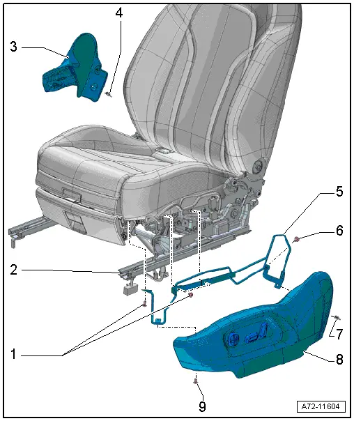
1 - Bolt
- Quantity: 3
- 8 Nm
2 - Front Seat
3 - Seat Side Trim on the Tunnel Side
- Removing and installing. Refer to → Chapter "Seat Side Trim on the Tunnel Side, Removing and Installing".
4 - Expanding Rivet
5 - Sill Panel Seat Side Trim Bracket
- Removing and installing. Refer to → Chapter "Seat Side Trim on Sill Panel Side, Removing and Installing, Power Front Seat".
6 - Bolt
- 8 Nm
7 - Expanding Rivet
8 - Seat Side Sill Panel Trim
- Removing and installing. Refer to → Chapter "Seat Side Trim on Sill Panel Side, Removing and Installing, Power Front Seat".
- Attach to the bracket and storage compartment
9 - Bolt
- 8 Nm
Overview - Seat Pan, Lumbar Support Adjustment Switch
1 - Seat Side Sill Panel Trim
- Removing and installing. Refer to → Chapter "Seat Side Trim on Sill Panel Side, Removing and Installing, Power Front Seat".
2 - Bolt
- 1.3 Nm
- Quantity: 2
3 - Driver Seat Lumbar Support Adjustment Switch -E176-
- Front passenger side Front Passenger Seat Lumbar Support Adjustment Switch -E177-
- Removing and installing. Refer to → Chapter "Driver/Front Passenger Seat Lumbar Support Adjustment Switch -E176-/-E177-, Removing and Installing".
Overview - Seat Pan, Power Seat Adjustment Control Head
1 - Seat Side Sill Panel Trim
- Removing and installing. Refer to → Chapter "Seat Side Trim on Sill Panel Side, Removing and Installing, Power Front Seat".
2 - Actuator
- For backrest adjustment
- clipped on
- Removing and installing. Refer to → Chapter "Driver/Front Passenger Seat Adjustment Control Head -E470-/-E471-, Removing and Installing".
- Press on until it engages audibly
3 - Actuator
- For seat adjustment
- Clipped on
- Removing and installing. Refer to → Chapter "Driver/Front Passenger Seat Adjustment Control Head -E470-/-E471-, Removing and Installing".
- Press on until it engages audibly
4 - Driver Seat Lumbar Support Adjustment Switch -E176-
- Front passenger side Front Passenger Seat Lumbar Support Adjustment Switch -E177-
- Removing and installing. Refer to → Chapter "Driver/Front Passenger Seat Lumbar Support Adjustment Switch -E176-/-E177-, Removing and Installing".
5 - Bolt
- 1.3 Nm
- Quantity: 2
6 - Bolt
- 1.3 Nm
- Quantity: 3
7 - Driver Seat Adjustment Control Head -E470-
- with:
- Driver Backrest Adjustment Switch -E96-
- Driver Seat Angle Adjustment Switch -E222-
- Driver Seat Forward/Back Adjustment Switch -E363-
- Driver Seat Height Adjustment Switch -E364-
- Front passenger side: Front Passenger Seat Adjustment Control Head
-E471- with:
- Front Passenger Seat Forward/Back Adjustment Switch -E64-
- Front Passenger Backrest Adjustment Switch -E98-
- Front Passenger Seat Angle Adjustment Button -E334-
- Front Passenger Seat Height Adjustment Switch -E365-
- Removing and installing. Refer to → Chapter "Driver/Front Passenger Seat Adjustment Control Head -E470-/-E471-, Removing and Installing".
Overview - Seat Pan, Seat Height Adjustment
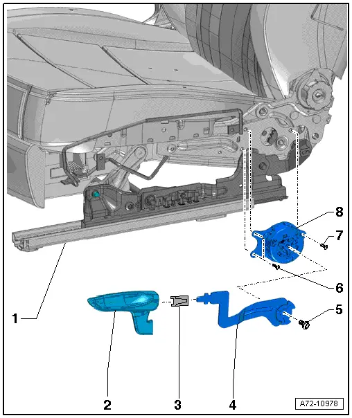
1 - Front Seat
- Manual
2 - Seat Height Adjustment Handle
- Always replace if removed
- Removing and installing. Refer to → Chapter "Seat Height Adjuster, Removing and Installing".
- Push the handle all the way on
3 - Clip
- Always replace if removed
- Installed position
4 - Lever
- For seat height adjustment handle
- Removing and installing. Refer to → Chapter "Seat Height Adjuster, Removing and Installing".
5 - Bolt
- 19.5 Nm
6 - Bolt
- 6 Nm
- Quantity: 2
7 - Bolt
- 6 Nm
8 - Seat Height Adjuster
- Removing and installing. Refer to → Chapter "Seat Height Adjuster, Removing and Installing".
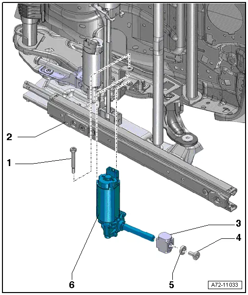
Overview - Seat Pan, Seat Height Adjustment Motor
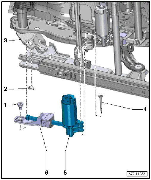
1 - Bolt
- 18 Nm
- Self-locking
- Replace
- Removing and Installing. Refer to → Chapter "Driver/Front Passenger Seat Height Adjustment Motor -V245-/-V246-, Removing and Installing".
- Threaded holes for bolts must be cleaned, for example, with a thread tap
2 - Not installed
3 - Seat pan
4 - Bolt
- 8 Nm
- Self-locking
- Replace
- Clean the threaded hole with a thread tap.
5 - Driver Seat Height Adjustment Motor -V245-
- Front passenger side: Front Passenger Seat Height Adjustment Motor -V246-
- Removing and installing. Refer to → Chapter "Driver/Front Passenger Seat Height Adjustment Motor -V245-/-V246-, Removing and Installing".
6 - Spindle guide
- Component of the seat height adjustment motor
Overview - Seat Pan, Seat Angle Adjuster
1 - Handle
- For seat angle adjuster
- Removing and installing. Refer to → Chapter "Seat Angle Adjustment Handle, Removing and Installing".
- Press until it engages completely
2 - Clip
- Replace the seat angle adjustment handle each time it is removed
- Installed position
3 - Bolt
- 6.5 Nm
- Self-locking
- Replace
- Threaded holes for bolts must be cleaned, for example, with a thread tap
4 - Shoulder pin
- Self-locking
- Replace
- Threaded hole for shoulder pin must be cleaned, for example, with thread cutter
- 6 Nm
5 - Seat Angle Adjuster
- Removing and installing. Refer to → Chapter "Seat Angle Adjuster, Removing and Installing".
Overview - Seat Pan, Seat Angle Adjustment Motor
1 - Bolt
- 8 Nm
- Self-locking
- Replace
- Clean the threaded hole with a thread tap.
2 - Seat Pan
3 - Spindle Nut
- Component of the angle adjustment motor
- Installed into the mount on the seat
4 - Bolt
- 8 Nm
- Self-locking
- Replace
- Clean the threaded hole with a thread tap.
5 - Washer
6 - Driver Seat Angle Adjustment Motor -V243-
- Front passenger side: Front Passenger Seat Angle Adjustment Motor -V224-
- Removing and installing. Refer to → Chapter "Driver/Front Passenger Seat Angle Adjustment Motor -V243-/-V244-, Removing and Installing".
READ NEXT:
 Overview - Seat Pan, Drawer
1 - Retaining Tab
2 - Drawer
3 - Bolt
1.5 Nm
4 - Bolt
1.5 Nm
5 - Mount
For the drawer
Removing and installing. Refer to
→&
Front Seat, Removing and Installing
Front Seat, Removing and Installing, Manual/Power
Special tools and workshop equipment
required
Universal Vehicle Protector -VAS871 001-
Airbag Lockout Adapter -VAS6282-
Removing
Airbag Adapter, Connecting and Disconnecting
Connectors, Disconnecting and Connecting at Connector Station
Connector assignment. Refer to
→ Wiring diagrams, Troubleshooting & Component locations.
Note
The connector statiSEE MORE:
Camera-based traffic sign recognition
Description
Applies to: vehicles with camera-based traffic sign recognition
Fig. 92 Instrument cluster: traffic sign recognition
The traffic sign recognition shows the traffic
signs detected by the front camera in the instrument
cluster display. Data from the navigation
system is also included in t
Tire Wear and Service Life
General Information
Note
Having the correct air pressure in the tires can also
decrease the amount of tire wear and increase the tire mileage.
Always make sure that the tires are inflated to the correct
air pressure.
Numerous demands are made on a tire.
Depending on the use o