
Audi Q3: MMI Bluetooth Hands-Free Calling Connector Assignments, 9ZX
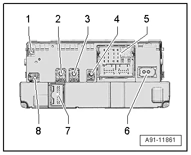
Information Electronics Control Module 1 -J794-
1 - Not Assigned
2 - 4-Pin Connector -T4u- to the External Audio Source Connection -R199-/Internet Access Control Module - J666-
3 - 4-Pin Connector -T4al- to the Front Information Display Control Head -J685-
4 - Not Assigned
5 - Connection block with four multi-pin connectors
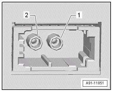
6 - MOST Bus
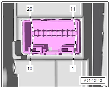
7 - 20-Pin Connector -T20k- to the Information Electronics Control Module 1 -J794-
8 - Not Assigned
 Note
Note
Unlisted connector terminals are not assigned.
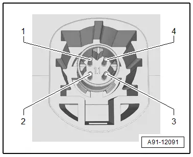
2 - 4-Pin Connector -T4u-
All pins are connected with the External Audio Source Connection -R199-/Internet Access Control Module -J666-.
1 - D (+)
2 - iPod recognized
3 - D (-)
4 - Ground
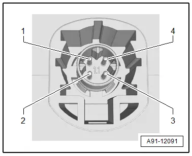
3 - 4-Pin Connector -T4al-
All pins are connected to the Front Information Display Control Head -J685-.
1 - LVDS (-)
2 - LIN
3 - LVDS (+)
4 - Ground
5 - Connection Block with Four Multi-Pin Connectors
A - 8-Pin Connector -T8ah-
2 - Power supply to the Information Electronics Control Module 1 -J794-, 20-Pin Connector -T20k-
3 - Wake Up to the Information Electronics Control Module 1 -J794-, 20-Pin Connector -T20k-
6 - Res MU to the Information Electronics Control Module 1 -J794-, 20-Pin Connector -T20k-
7 - Ring-break Diagnostic Cable
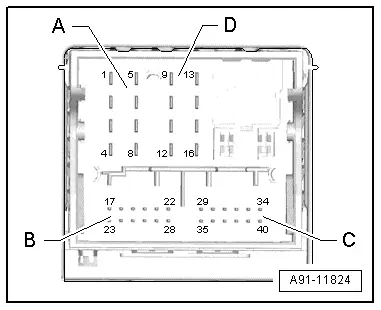
B - 12-Pin Connector -T12x-
21 - CVBS cable (-) for the Rearview Camera System Control Module -J772-
24 - Microphone input (+) from Microphone Unit In Front Roof Module -R164-, Telephone Microphone -R38-
25 - Microphone input (-) from Microphone Unit In Front Roof Module -R164-, Telephone Microphone -R38-
27 - CVBS cable (+) for the Rearview Camera System Control Module -J772-
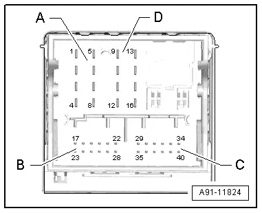
C - 12-Pin Connector -T12k-
All pins are connected to the External Audio Source Connection -R199-.
29 - LF-In Ground
30 - Right LF-In
31 - USB, +5 V. not on the Internet Access Control Module -J666-, UE2
32 - USB, Ground
33 - iPod, ACC Power
34 - Detect, not on the Internet Access Control Module -J666-, UE2
35 - Left LF-In
36 - LF-In ground shielding
37 - CVBS cable (+)
38 - CVBS cable (-)
39 - iPod data
40 - iPod data
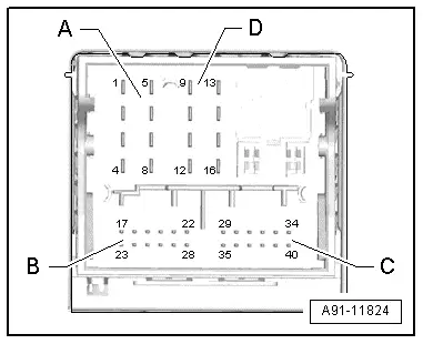
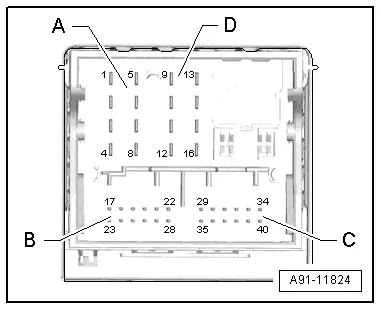
Following pins are also still connected with the Internet Access Control Module -J666-, UE2.
31 - USB, +5 V
32 - USB, Ground
34 - Detect
D - 8-Pin Connector -T8ao-
10 - Data from Information Electronics Control Module 1 -J794-, 20-Pin Connector -T20k-
11 - Data to Information Electronics Control Module 1 -J794-, 20-Pin Connector -T20k-
12 - Terminal 31
14 - Res BT from Information Electronics Control Module 1 -J794-, 20-Pin Connector -T20k-
15 - Terminal 30
16 - Ground to Information Electronics Control Module 1 -J794-, 20-Pin Connector -T20k-
6 - MOST bus
1 - Input
2 - Output
7 - 20-Pin Connector -T20k-
6 - Wake UP to the Information Electronics Control Module 1 -J794-
7 - Power supply from the Information Electronics Control Module 1 -J794-
8 - Ground to the Information Electronics Control Module 1 -J794-
13 - Res MU from the Information Electronics Control Module 1 -J794-
14 - Res MU to the Information Electronics Control Module 1 -J794-
15 - Information Electronics Control Module 1 -J794- data
16 - Data from Information Electronics Control Module 1 -J794-
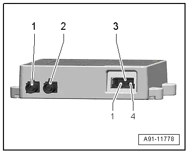
Cellular Telephone Amplifier -R86-, Connector Assignment
Cellular Telephone Amplifier -R86-
1 - GSM connection from Roof Antenna -R216-
2 - Antenna connection to the Telephone Baseplate -R126-
3 - 4-Pin Connector -T4ak-
 Note
Note
Unlisted connector terminals are not assigned.
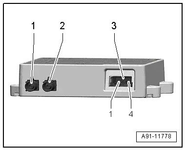
3 - 4-Pin Connector -T4ak-
1 - Terminal 30
2 - Terminal 31
3 - Switch-on signal from Information Electronics Control Module 1 -J794-
4 - Control pin (not used)
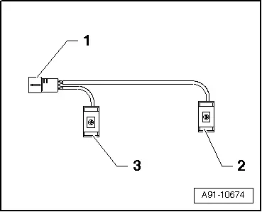
Connector Assignment, Microphone Unit
1 - 4-Pin Connector -T4bg-
1 - Microphone 1, Telephone Microphone -R38- to the Information Electronics Control Module 1 -J794-
2 - Microphone 1, Telephone Microphone -R38- to the Information Electronics Control Module 1 -J794-
3 - Microphone 2, Interior Microphone -R74- to the Digital Sound System Control Module -J525-
4 - Microphone 2, Interior Microphone -R74- to the Digital Sound System Control Module -J525-
2 - Microphone 1, Telephone Microphone -R38-
3 - Microphone 2, Interior Microphone -R74-
READ NEXT:
 Overview - Navigation System
Overview - Navigation System, General Information
The navigation system is available on vehicles with
Ready4Nav (7Q4), Navigation packet (7T2) and MMI navigation plus
(7T6).
The navigation s
Chip Card Reader Control Module, Removing and Installing
The Chip Card Reader Control Module -J676--1-
is located inside the glove compartment
-2-.
Removing
- Turn off the ignition and all electrical equipment and
remove the ignition key.
-&nbSEE MORE:
Setup
Connecting a mobile phone via Bluetooth
Applies to: vehicles with telephone
Requirement: the vehicle must be stationary and
the ignition must be switched on. The Bluetooth
settings must be open on your mobile device during
the connection setup. The mobile device to be
connected must not be actively
Safety precautions
Explanation of warning symbols:
Observe all warnings - there is
a risk for injury!
Always follow the instructions
in the operating manual.
Electrolyte fluid is highly
corrosive. Always wear protective gloves and eye protection.
First aid: if electrolyte fluid enters the
eyes, immediately flus