Audi Q3: Relay and Fuse Carriers Behind Instrument Panel on Driver Side, Removing and Installing
Relay Carrier on Vehicle Electrical System Control Module, Removing and Installing
Removing
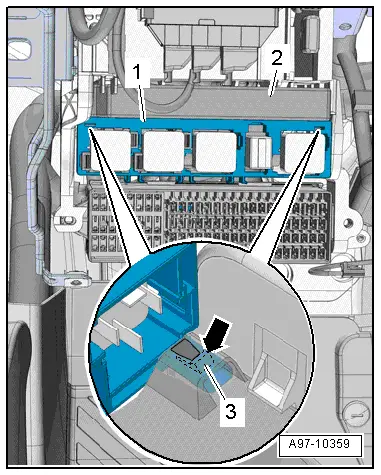
- Remove the driver side instrument panel cover. Refer to → Body Interior; Rep. Gr.68; Storage Compartments/Covers; Driver Side Instrument Panel Cover, Removing and Installing.
- Release the tab -3- with a screwdriver and remove the relay panel -2- from the vehicle electrical system control module -1-.
 Note
Note
Disregard -2-.
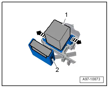
- Open the retainers in direction of -arrows- and remove the relay -1- and the control modules from the relay carriers.
 Note
Note
Check the exact assignment in the current wiring diagram. Refer to → Wiring diagrams, Troubleshooting & Component locations.

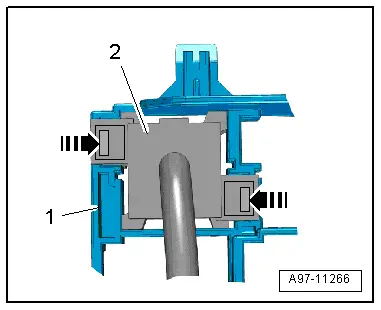
- Release the retainers -arrows- and remove the relay carrier -2- from the relay/fuse panel -1- to the rear.
Installing
Install in reverse order of removal. Note the following:
- Install the driver side instrument panel cover. Refer to → Body Interior; Rep. Gr.68; Storage Compartments/Covers; Driver Side Instrument Panel Cover, Removing and Installing.

Relay Carrier, Under Instrument Panel on Left Side, Removing and Installing
Removing
- Remove the vehicle electrical system control module. Refer to → Chapter "Vehicle Electrical System Control Module -J519-, Removing and Installing".
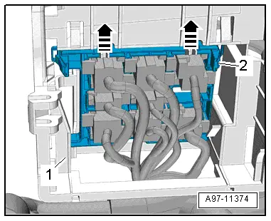
- Disengage the relay panel -2- from the mount -1- downward, to do this push the springs in the direction of -arrow-.
 Note
Note
Disregard -2-.
- Open the retainers -arrows- and remove the relay -1- and the control modules from the relay carriers.
 Note
Note
Check the exact assignment in the current wiring diagram. Refer to → Wiring diagrams, Troubleshooting & Component locations.
- Release the retainers -arrows- and remove the relay carrier -2- from the relay/fuse panel -1- to the rear.
Installing
Install in reverse order of removal. Note the following:
- Install the vehicle electrical system control module. Refer to → Chapter "Vehicle Electrical System Control Module -J519-, Removing and Installing".
Relay/Fuse Carrier Mount with Vehicle Electrical System Control Module -J519-, Removing and Installing
Removing
- Remove the fuse panel C and set aside with the wires still attached. Refer to → Chapter "Fuse Panel C -SC-, Removing and Installing".
- Remove the vehicle electrical system control module and set aside with the wires attached and if equipped with the relay carrier still attached. Refer to → Chapter "Vehicle Electrical System Control Module -J519-, Removing and Installing".
- Remove the relay carrier under left instrument panel. Refer to → Chapter "Relay Carrier, Under Instrument Panel on Left Side, Removing and Installing".
- Remove the instrument cluster. Refer to → Chapter "Instrument Cluster with Instrument Cluster Control Module -J285-, Removing and Installing".
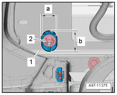
- To reach the upper nut -2- from the mount for the control modules, relay and fuse panel, drill an oblong hole into the instrument cluster mount -1- as shown.
- Dimension -a- = 22 mm.
- Dimension -b- = 23 mm.
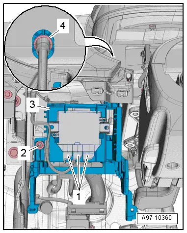
- Remove the nuts -2 and 4-.
- If equipped disconnect the connector -1- on the vehicle positioning system interface control module.
- If equipped disconnect the connector on the buzzer.
- Disengage the mount -3- for the control module, relay and fuse panel from the instrument panel central tube and remove.
Installing
Install in reverse order of removal. Note the following:
- Install the relay carrier under left instrument panel. Refer to → Chapter "Relay Carrier, Under Instrument Panel on Left Side, Removing and Installing".
- Install the vehicle electrical system control module. Refer to → Chapter "Vehicle Electrical System Control Module -J519-, Removing and Installing".
- Install fuse panel C. Refer to → Chapter "Fuse Panel C -SC-, Removing and Installing".
READ NEXT:
 Control Modules
Component Location Overview - Control Modules
Component Location Overview - Control Modules
1 - Vehicle Electrical System Control Module -J519-
Removing and installing. Refer to
â†
Connectors
Connector Component Location Overview
1 - Right Front Door Cut-Off Connector
Disconnecting. Refer to
→ Chapter "Left Door Cut-Off Connector, Disconnecting".
2 - SEE MORE:
Bench Seat/Single Seat, Removing and Installing
Removing
- Move the front seats all the way forward.
- Unclip the child seat anchor guides (quantity: four)
-1- from anchorages. Refer to
→ Chapter "Child Seat Anchor Guide, Removing and Installing,
Rear".
- With both hands, grasp the rear bench seat under the seat
f
Rear Brake Caliper, Removing and Installing
Brake Caliper, Removing and Installing, Brake 1KU
Note
In the following description the brake caliper is removed
with the brake carrier and pads. The brake hose remains
connected.
Special tools and workshop equipment
required
Torque Wrench 1332 40-200Nm -VAG1332-
Removing
