Audi Q3: Connector Assignments, Cell Phone Preparation MMI, 9ZF
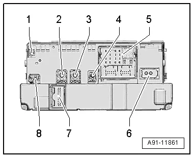
Information Electronics Control Module 1 -J794-
1 - Not Assigned
2 - 4-Pin Connector -T4u- to the External Audio Source Connection -R199-/Internet Access Control Module - J666-
3 - 4-Pin Connector -T4al- to the Front Information Display Control Head -J685-
4 - Not Assigned
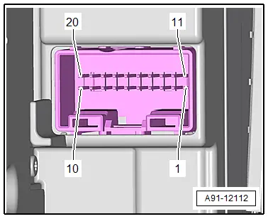
5 - Connection block with four multi-pin connectors
6 - MOST Bus
7 - 20-Pin Connector -T20k- to the Information Electronics Control Module 1 -J794-
8 - Not Assigned
 Note
Note
Unlisted connector terminals are not assigned.
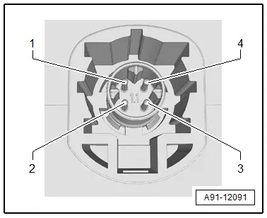
2 - 4-Pin Connector -T4u-
All pins are connected with the External Audio Source Connection -R199-/Internet Access Control Module -J666-.
1 - D (+)
2 - iPod recognized
3 - D (-)
4 - Ground
3 - 4-Pin Connector -T4al-
All pins are connected to the Front Information Display Control Head -J685-.
1 - LVDS (-)
2 - LIN
3 - LVDS (+)
4 - Ground

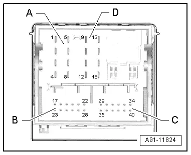
5 - Connection Block with Four Multi-Pin Connectors
A - 8-Pin Connector -T8ah-
1 - LF mute wire from preliminary setup for cell phone preparation
2 - Power supply to the Information Electronics Control Module 1 -J794-, 20-Pin Connector -T20k-
3 - Wake Up to the Information Electronics Control Module 1 -J794-, 20-Pin Connector -T20k-
4 - Not Assigned
5 - Switch-on signal to Telephone Baseplate -R126-/Cellular Telephone Amplifier -R86-
6 - Res MU to the Information Electronics Control Module 1 -J794-, 20-Pin Connector -T20k-
7 - Ring-break Diagnostic Cable

B - 12-Pin Connector -T12x-
21 - CVBS cable (-) for the Rearview Camera System Control Module -J772-
24 - Microphone input (+) from Microphone Unit In Front Roof Module -R164-, Telephone Microphone -R38-
25 - Microphone input (-) from Microphone Unit In Front Roof Module -R164-, Telephone Microphone -R38-
27 - CVBS cable (+) for the Rearview Camera System Control Module -J772-

C -12-Pin Connector -T12k-
All pins are connected to the External Audio Source Connection -R199-.
29 - LF-In Ground
30 - Right LF-In
31 - USB, +5 V. not on the Internet Access Control Module -J666-, UE2
32 - USB, Ground
33 - iPod, ACC Power
34 - Detect, not on the Internet Access Control Module -J666-, UE2
35 - Left LF-In
36 - LF-In ground shielding
37 - CVBS cable (+)
38 - CVBS cable (-)
39 - iPod data
40 - iPod data
Following pins are also still connected with the Internet Access Control Module -J666-, UE2.
31 - USB, +5 V
32 - USB, Ground
34 - Detect

D - 8-Pin Connector -T8ao-
10 - Data from Information Electronics Control Module 1 -J794-, 20-Pin Connector -T20k-
11 - Data to Information Electronics Control Module 1 -J794-, 20-Pin Connector -T20k-
12 - Terminal 31
13 - DIAG signal from Telephone Baseplate -R126-
14 - Res BT from Information Electronics Control Module 1 -J794-, 20-Pin Connector -T20k-
15 - Terminal 30
16 - Ground to Information Electronics Control Module 1 -J794-, 20-Pin Connector -T20k-
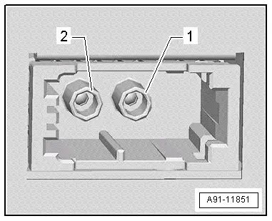
6 - MOST bus
1 - Input
2 - Output
7 - 20-Pin Connector -T20k-
6 - Wake UP to the Information Electronics Control Module 1 -J794-
7 - Power supply from the Information Electronics Control Module 1 -J794-
8 - Ground to the Information Electronics Control Module 1 -J794-
13 - Res MU from the Information Electronics Control Module 1 -J794-
14 - Res MU to the Information Electronics Control Module 1 -J794-
15 - Information Electronics Control Module 1 -J794- data
16 - Data from Information Electronics Control Module 1 -J794-
Connector Assignment, Cell Phone Preparation Preliminary Setup
 Note
Note
Unlisted connector terminals are not assigned.
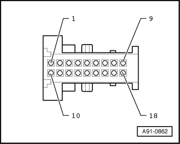
Multi-Pin Connector. 18-pin
1 - Terminal 31
4 - LF mute to the Information Electronics Control Module 1 -J794-
7 - LF (-) to Radio -R-
9 - Microphone input (-) from Microphone Unit In Front Roof Module -R164-, Telephone Microphone -R38-
10 - Terminal 15
11 - Terminal 30
16 - LF (+) to Radio -R-
18 - Microphone input (+) from Microphone Unit In Front Roof Module -R164-, Telephone Microphone -R38-
READ NEXT:
 Connector Assignment, Bluetooth Hands-Free Calling Concert MOST, 9ZX
Information Electronics Control Module 1 -J794-
1 - Connector AM/FM1 from the Antenna Amplifier -R24- (Radio
Antenna 2 -R93-)
2 - DAB connection from Antenna Amplifier 4 -R113-
MMI Bluetooth Hands-Free Calling Connector Assignments, 9ZX
Information Electronics Control Module 1 -J794-
1 - Not Assigned
2 - 4-Pin Connector -T4u- to the External Audio Source
Connection -R199-/Internet Access Control Module - J666-SEE MORE:
Overview - Trim Molding and Covers
1 - Front Door Gap Cover
Removing and installing. Refer to
→ Chapter "Door Gap Cover, Removing and Installing".
2 - Clip
Quantity: 5
3 - Grommet
For the clip
4 - Front Door
5 - Side Window
6 - Trim Strip
Battery Charger -VAS5900-
WARNING
Risk of injury. Follow all warning messages and
safety precautions. Refer to
→ Chapter "Warnings and Safety Precautions".
WARNING
Do not check or charge a Battery -A- when the visual
indicator has "no color or is
bright yellow". Jump starting must not be