
Audi Q3: Connector Assignments, Cell Phone Preparation Concert MOST, 9ZF
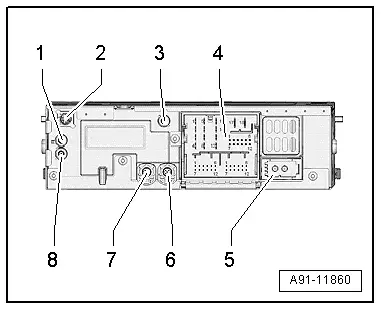
Information Electronics Control Module 1 -J794-
1 - Connector AM/FM1 from the Antenna Amplifier -R24- (Radio Antenna 2 -R93-)
2 - DAB connection from Antenna Amplifier 4 -R113-, Digital Radio Antenna -R183-
3 - Not installed
4 - Black connection block with four multi-pin connectors
5 - MOST Bus
6 - 4-Pin Connector -T4ap- to the External Audio Source Connection -R199-/Internet Access Control Module - J666-
7 - 4-Pin Connector -T4d- to the Front Information Display Control Head -J685-
8 - Connection FM2 from Antenna Amplifier 3 -R112-, Antenna -R11-
Only North America and QV8
1 - Connector AM/FM1 from the Antenna Amplifier -R24- (Radio Antenna 2 -R93-)
2 - SAT connection from Roof Antenna -R216-, Satellite Antenna -R170-
3 - Not installed
4 - Connection block with four multi-pin connectors
5 - MOST Bus
6 - 4-Pin Connector -T4ap- from the External Audio Source Connection -R199-/Internet Access Control Module -J666-
7 - 4-Pin Connector -T4d- to the Front Information Display Control Head -J685-
8 - Connection FM2 from Antenna Amplifier 3 -R112-, Antenna -R11-
 Note
Note
Unlisted connector terminals are not assigned.
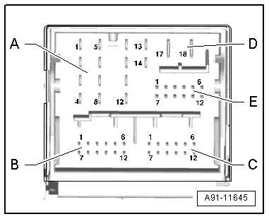
4 - Connection Block with Four Multi-Pin Connectors
A - 8-Pin Connector -T8ag-
1 - Right rear speaker (+)
2 - Right front speaker (+)
3 - Left front speaker (+)
4 - Left rear speaker (+)
5 - Right rear speaker (-)
6 - Right front speaker (-)
7 - Left front speaker (-)
8 - Left rear speaker (-)
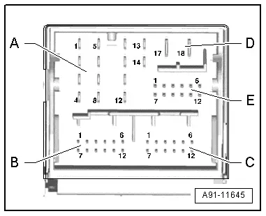
B - 12-Pin Connector -T12x-
4 - Microphone input (+) from Microphone Unit In Front Roof Module -R164-, Telephone Microphone -R38-
5 - CVBS cable (-) for the Rearview Camera System Control Module -J772-
6 - DIAG signal from Telephone Baseplate -R126-
11 - CVBS cable (+) for the Rearview Camera System Control Module -J772-
12 - Microphone input (-) from Microphone Unit In Front Roof Module -R164-, Telephone Microphone -R38-
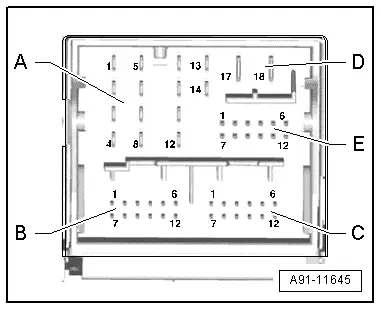
C - 12-Pin Connector -T12y-
All pins are connected to the External Audio Source Connection -R199-.
1 - LF-In Ground
2 - Right LF-In
3 - USB, +5 V. not on the Internet Access Control Module -J666-, UE2
4 - USB, Ground
5 - iPod, ACC Power
6 - Detect, not on the Internet Access Control Module -J666-, UE2
7 - Left LF-In
8 - LF-In ground shielding
9 - CVBS cable (+)
10 - CVBS cable (-)
11 - iPod data
12 - iPod data
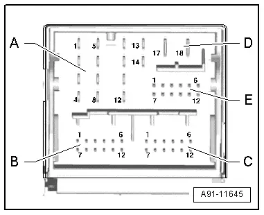
Following pins are also still connected with the Internet Access Control Module -J666-, UE2.
3 - USB, +5 V
4 - USB, Ground
6 - Detect
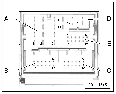
D - 8-Pin Connector -T8j-
9 - Subwoofer -R211-
10 - Center Speaker -R208-
13 - Subwoofer -R211-
14 - Center Speaker -R208-
17 - Terminal 31
18 - Terminal 30
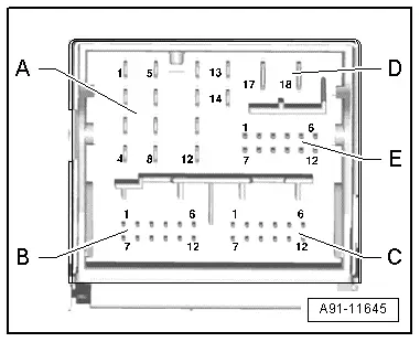
E - 12-Pin Connector -T12w-
7 - Ring-break Diagnostic Cable
12 - Switch-on signal to Telephone Baseplate -R126-/Cellular Telephone Amplifier -R86-
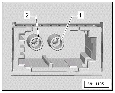
5 - MOST bus
1 - Input
2 - Output
6 - 4-Pin Connector -T4ap-
All pins are connected with the External Audio Source Connection -R199-/Internet Access Control Module -J666-.
1 - D (+)
2 - iPod recognized
3 - D (-)
4 - Ground
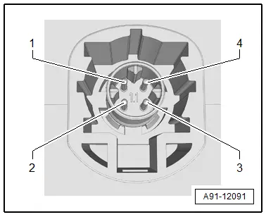
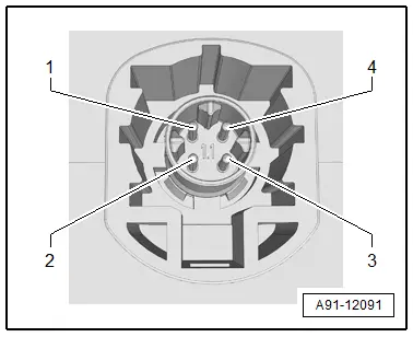
7 - 4-Pin Connector -T4d-
All pins are connected to the Front Information Display Control Head -J685-.
1 - LVDS (-)
2 - LIN
3 - LVDS (+)
4 - Ground
READ NEXT:
 Connector Assignments, Cell Phone Preparation MMI, 9ZF
Information Electronics Control Module 1 -J794-
1 - Not Assigned
2 - 4-Pin Connector -T4u- to the External Audio Source
Connection -R199-/Internet Access Control Mo
Connector Assignment, Bluetooth Hands-Free Calling Concert MOST, 9ZX
Information Electronics Control Module 1 -J794-
1 - Connector AM/FM1 from the Antenna Amplifier -R24- (Radio
Antenna 2 -R93-)
2 - DAB connection from Antenna Amplifier 4 -R113-
MMI Bluetooth Hands-Free Calling Connector Assignments, 9ZX
Information Electronics Control Module 1 -J794-
1 - Not Assigned
2 - 4-Pin Connector -T4u- to the External Audio Source
Connection -R199-/Internet Access Control Module - J666-SEE MORE:
Accelerator pedal
You can accelerate the vehicle using the accelerator
pedal.
Maximum acceleration
If you press the accelerator pedal all the way
down, the motor's full power will be used and
you will reach maximum acceleration, also called
"kick-down".
WARNING
The driving wheels could spin and the vehicle
could swer
Lane departure warning
General information
Applies to: vehicles with lane departure warning
The lane departure warning can detect lane
marker lines within the limits of the system. If
you are approaching a detected lane marker and
it appears likely that you will leave the lane, the
system can warn you with corrective stee